background image

11 

With this feature enabled on an interface, when the interface goes down, the system enables link 
flapping detection. During the link flapping detection interval, if the number of detected flaps reaches 
or exceeds the link flapping detection threshold, the system shuts down the interface. 

Configuration restrictions and guidelines 

This feature takes effect only if it is configured in both the system view and interface view. 

The 

dampening

link-delay

, and 

port link-flap protect enable

 commands are mutually exclusive 

on an Ethernet interface. 

To bring up an interface that has been  shut down by link flapping protection, execute the 

undo 

shutdown

 command. 

In the 

display interface 

command output, the 

Link-Flap DOWN

 value of the 

Current state

 field 

indicates that the interface has been shut down by link flapping protection. 

Configuration procedure 

To enable link flapping protection on an Ethernet interface: 


Step 

Command 

Remarks 

1. 

Enter system view. 

system-view


N/A 

2. 

Enable link flapping 
protection globally. 

link-flap protect enable


By default, link flapping protection 
is disabled globally. 

3. 

Enter Ethernet interface 
view. 

interface interface-type 
interface-number


N/A 

4. 

Enable link flapping 
protection on the Ethernet 
interface. 

port link-flap protect enable


[


interval


interval


|


threshold


threshold


]


*


By default, link flapping protection 
is disabled on an Ethernet 
interface. 


Configuring FEC 

About FEC 

The forward error correction (FEC) feature corrects packet errors to improve transmission quality. It 
attaches correction information to a packet at the sending end, and corrects error codes generated 
during transmission at the receiving end based on the correction information. You can set the FEC 
mode as needed. 

Restrictions and guidelines 

This feature is supported only on 100-GE interfaces. 

A  100-GE  interface connected through a copper cable or installed with a 40-Gbps transceiver 
module does not support FEC. If FEC has been configured on the interface, use the 

undo port fec 

mode

 command to restore the default.  

When the FEC mode is set to 

auto

 on an interface, the actual FEC mode of the interface depends on 

the model of the transceiver module installed. To view the actual FEC mode, see the 

FEC mode

 field 

in the 

display interface

 command output.  

Make sure you set the same FEC mode for both interfaces of a link.  

Procedure 

Step 

Command 

Remarks 

1. 

Enter system view. 

system-view


N/A 

2. 

Enter Ethernet interface 
view. 

interface interface-type 
interface-number


N/A 

Содержание S7500X Series

Страница 1: ...H3C S7500X Switch Series Interface Configuration Guide New H3C Technologies Co Ltd http www h3c com Software version Release 7585P05 and later versions Document version 6W100 20200529...

Страница 2: ...H3C Technologies Co Ltd any trademarks that may be mentioned in this document are the property of their respective owners Notice The information in this document is subject to change without notice A...

Страница 3: ...optional x y Braces enclose a set of required syntax choices separated by vertical bars from which you select one x y Square brackets enclose a set of optional syntax choices separated by vertical ba...

Страница 4: ...s a Layer 2 or Layer 3 switch or a router that supports Layer 2 forwarding and other Layer 2 features Represents an access controller a unified wired WLAN module or the access controller engine on a u...

Страница 5: ...Documentation feedback You can e mail your comments about product documentation to info h3c com We appreciate your comments...

Страница 6: ...i Contents Bulk configuring interfaces 1 Configuration restrictions and guidelines 1 Configuration procedure 1 Displaying and maintaining bulk interface configuration 2...

Страница 7: ...terface range the longer the command execution time The maximum number of interface range names is limited only by the system resources To guarantee bulk interface configuration performance configure...

Страница 8: ...ace range to enter the interface range view 3 Optional Display commands available for the first interface in the interface range Enter a question mark at the interface range prompt N A 4 Use available...

Страница 9: ...rnet interface 9 Enabling link flapping protection on an interface 10 Configuring FEC 11 Enabling loopback testing on an Ethernet interface 12 Configuring generic flow control on an Ethernet interface...

Страница 10: ...r You can connect the interface to a PC for software loading and system debugging or connect it to a remote NMS for remote system management Restrictions and guidelines The management Ethernet interfa...

Страница 11: ...faces see Configuring a Layer 3 Ethernet interface or subinterface Configuring a combo interface single combo interface A combo interface is a logical interface that physically comprises one fiber com...

Страница 12: ...ot the interface card to make the configuration take effect Do not assign the changed interfaces to any non default MDC before rebooting the interface card To split a 40 GE interface into four 10 GE b...

Страница 13: ...on default MDC before rebooting the interface module For this configuration to survive a reboot save the running configuration before rebooting the device Changing 100 GE interfaces to 40 GE interface...

Страница 14: ...with copper port transceiver modules installed on the following interface modules FD interface modules SC interface modules LSQM2GP24TSSC0 LSQM2GP44TSSC0 LSQM2GT24PTSSC0 LSQM2GT24TSSC0 LSQM2GT48SC0 L...

Страница 15: ...ed bandwidth in kbps is the interface baud rate divided by 1000 7 Restore the default settings for the Ethernet interface default N A 8 Bring up the Ethernet interface undo shutdown B y default an Eth...

Страница 16: ...oups see Network Management and Monitoring Configuration Guide To configure the link mode of an Ethernet interface Step Command Remarks 1 Enter system view system view N A 2 Enter Ethernet interface v...

Страница 17: ...press only link down events only link up events or both If an event of the specified type still exists when the suppression interval expires the system reports the event to the CPU Configuration restr...

Страница 18: ...e the interface does not report its state changes to the CPU For state change events the interface only generates SNMP traps and log messages Reuse limit When the accumulated penalty decreases to this...

Страница 19: ...edure To configure dampening on an Ethernet interface Step Command Remarks 1 Enter system view system view N A 2 Enter Ethernet interface view interface interface type interface number N A 3 Enable da...

Страница 20: ...ce interface type interface number N A 4 Enable link flapping protection on the Ethernet interface port link flap protect enable interval interval threshold threshold By default link flapping protecti...

Страница 21: ...does not forward data traffic The shutdown port up mode and loopback commands are mutually exclusive Enabling loopback testing on an interface will invalidate the voice VLAN MAC learning limit MAC ad...

Страница 22: ...the flow control command at the other end To enable both ends of a link to handle traffic congestion configure the flow control command at both ends Configuration restrictions and guidelines This feat...

Страница 23: ...type interface number N A 3 Set the statistics polling interval for the Ethernet interface flow interval interval By default the statistics polling interval is 300 seconds To display the interface st...

Страница 24: ...rnet port does not support this feature if the port is shut down by a protocol or by using the shutdown command A fiber Ethernet port does not support this feature if the port joins an aggregate group...

Страница 25: ...ow these restrictions and guidelines For the traffic suppression result to be determined do not configure storm control together with storm suppression for the same type of traffic For more informatio...

Страница 26: ...blocked traffic drops below the lower threshold the interface does not automatically come up To bring up the interface use the undo shutdown command or disable the storm control feature You can confi...

Страница 27: ...outputs log messages when monitored traffic exceeds the upper threshold or drops below the lower threshold after exceeding the upper threshold 7 Optional Enable the Ethernet interface to send storm co...

Страница 28: ...terface has eight pins each of which plays a dedicated role For example pins 1 and 2 transmit signals and pins 3 and 6 receive signals You can use both crossover and straight through Ethernet cables t...

Страница 29: ...result includes the cable s status and some physical parameters If any fault is detected the test result shows the length from the local port to the faulty point To test the cable connection of an Eth...

Страница 30: ...Ethernet interface or subinterface mtu size The default setting is 1500 bytes Displaying and maintaining an Ethernet interface or subinterface Execute display commands in any view and reset commands...

Страница 31: ...ethernet statistics slot slot number In IRF mode Display the Ethernet module statistics display ethernet statistics chassis chassis number slot slot number Clear interface or subinterface statistics...

Страница 32: ...ing loopback null and inloopback interfaces 1 Configuring a loopback interface 1 Configuring a null interface 1 Configuring an inloopback interface 2 Displaying and maintaining loopback null and inloo...

Страница 33: ...device itself so the device does not forward these packets Using a loopback interface in dynamic routing protocols With no router ID configured for a dynamic routing protocol the system selects the hi...

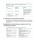
Страница 34: ...e created by the system which cannot be configured or deleted The physical layer and link layer protocol states of an inloopback interface are always up All IP packets sent to an inloopback interface...

Отзывы: