background image


5


Figure 3


Rear panel of the S5500-28C-EI-DC switch 


(1) –48V DC power input 

(2) RPS power input (shipped with a protective cover) 

(3) Grounding screw


(4) Interface card slot 1 (MOD1)


(5) Interface card slot 2 (MOD2)


NOTE: 

The S5500-28C-EI/S5500-28C-EI-DC is shipped with the two expansion interface card slots covered by
filler panels. You can select one or two interface cards for your switch as needed. For the interface cards

available for the S5500-EI Switch Series, see "

Interface cards

." For how to install an interface card,


see

"

Installing and removing an interface card

." 


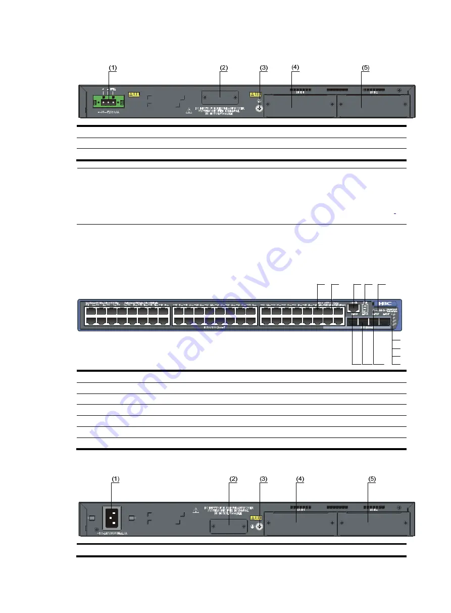
S5500-52C-EI 

Figure 4


Front panel of the S5500-52C-EI switch 


(1) 10/100/1000 Base-T auto-sensing Ethernet port


(2) 10/100/1000 Base-T auto-sensing Ethernet port status LED 
(3) Console port


(4) Seven-segment LED


(5) Port mode LED (Mode) 

(6) System status LED (PWR) 

(7) RPS status LED (RPS) 

(8) Interface card 1 status LED (MOD1) 

(9) Interface card 2 status LED (MOD2)


(10) Port status LED mode switching button


(11) 1000 Base-X SFP port 

(12) 1000Base-X SFP port status LED 


Figure 5


Rear panel of the S5500-52C-EI switch 


(1) AC power input


(2) RPS power input (shipped with a protective cover)


(1)

(2)

(3) (4)

(5)

(6)

(7)

(8)

(9)

(10)

(11)

(12)

Содержание S5500-EI series

Страница 1: ...H3C S5500 EI Switch Series Installation Guide Hangzhou H3C Technologies Co Ltd http www h3c com Document version 20130630 C 1 04...

Страница 2: ...d All other trademarks that may be mentioned in this manual are the property of their respective owners Notice The information in this document is subject to change without notice Every effort has bee...

Страница 3: ...Convention Description Boldface Bold text represents commands and keywords that you enter literally as shown Italic Italic text represents arguments that you replace with actual values Square brackets...

Страница 4: ...y CAUTION An alert that calls attention to important information that if not understood or followed can result in data loss data corruption or damage to hardware or software IMPORTANT An alert that ca...

Страница 5: ...be the specifications installation and replacement of RPSs User manuals for interface cards Describe the specifications installation and replacement of expansion interface cards H3C Low End Series Eth...

Страница 6: ...ts Solutions Provides information about products and technologies as well as solutions Technical Support Documents Software Download Provides the documentation released with the software version Techn...

Страница 7: ...e LED 13 Seven segment LED 13 10 100 1000Base T auto sensing Ethernet port status LED 14 SFP port status LED 15 Interface card status LED 16 Hot swappable power modules 16 Interface cards 17 SFP SFP X...

Страница 8: ...and removing an interface card 42 Installing an interface card 42 Removing an interface card 43 Installing and removing a dedicated CX4 SFP cable 43 Forming an IRF virtual device 44 Flow for forming...

Страница 9: ...se X SFP port 48 10 100 1000Base T auto sensing Ethernet port 4 1000Base X SFP port 8 10 100 1000Base T auto sensing Ethernet port 24 1000Base X SFP port The last four 10 100 1000Base T Ethernet ports...

Страница 10: ...to 63 Hz 48V DC Rated voltage range 48 VDC to 60 VDC Input voltage range 36 VDC to 72 VDC You can use the 48 VDC power supply in the equipment room or an external RPS power supply unit recommended by...

Страница 11: ...port 1 10GBase T interface card LSPM1XGT2P supporting IRF Power supply system S5500 28C PWR EI and S5500 52C PWR EI are each designed with two fixed power receptacles an AC receptacle and an RPS rece...

Страница 12: ...r panels S5500 28C EI S5500 28C EI DC Figure 1 Front panel of the S5500 28C EI S5500 28C EI DC switch 1 10 100 1000 Base T auto sensing Ethernet port 2 10 100 1000 Base T auto sensing Ethernet port st...

Страница 13: ...rds For how to install an interface card see Installing and removing an interface card S5500 52C EI Figure 4 Front panel of the S5500 52C EI switch 1 10 100 1000 Base T auto sensing Ethernet port 2 10...

Страница 14: ...witch 1 SFP port 2 SFP port status LED 3 10 100 1000 Base T auto sensing Ethernet port 4 10 100 1000 Base T auto sensing Ethernet port status LED 5 Console port 6 Port status LED mode switching button...

Страница 15: ...emoving a hot swappable power module S5500 28C PWR EI The S5500 28C PWR EI includes two models PoE and PoE The front panels of the PoE and PoE models are the same in appearance See Figure 8 The PoE mo...

Страница 16: ...ou can select one or two interface cards for your switch as needed For the interface cards available for the S5500 EI Switch Series see Interface cards For how to install an interface card see Install...

Страница 17: ...D1 9 Interface card 2 status LED MOD2 10 Port status LED mode switching button 11 1000 Base X SFP port 12 1000Base X SFP port status LED Figure 12 Rear panel of the S5500 52C PWR EI switch PoE model 1...

Страница 18: ...te 9600 bps default to 115200 bps Service Provides connection to an ASCII terminal Provides connection to the serial port of a local or remote through a pair of modems PC running terminal emulation pr...

Страница 19: ...thernet 1 0 46 GigabitEthernet 1 0 50 GigabitEthernet 1 0 48 GigabitEthernet 1 0 51 GigabitEthernet 1 0 45 GigabitEthernet 1 0 52 GigabitEthernet 1 0 47 S5500 28F EI GigabitEthernet 1 0 17 GigabitEthe...

Страница 20: ...ule is installed in the power module slot and the power output is normal Steady yellow A power module is installed in the power module slot but the power module is experiencing an output error or is n...

Страница 21: ...tion LED Status Description Mode Steady green Port status LEDs are showing port rates Flashing green 1 Hz available only for the S5500 28C PWR EI and S5500 52C PWR EI Port status LEDs are showing the...

Страница 22: ...tem status LED and the port mode LED on the S5500 28C PWR EI or S5500 52C PWR EI that supports PoE can display the PoE power consumption percentage of the switch For relevant information see Table 12...

Страница 23: ...higher than the maximum or currently available PoE output power on the port Steady yellow The port is experiencing a PoE failure The devices attached to the port are not powered devices PDs so the po...

Страница 24: ...is present on the port Interface card status LED Table 15 Interface card status LED description Mark Status Description MOD1 MOD2 Green The interface card is in position and operates correctly Flashi...

Страница 25: ...d description Card model Name Description Remarks LSPM2GP2P 2 port GE SFP optical interface card Provides two Gbps SFP fiber ports Supports SFP transceiver modules except SFP GE T listed in Table 18 L...

Страница 26: ...m LC 50 125 m multimode optical fiber 550 m 1804 46 ft 62 5 125 m multimode optical fiber 275 m 902 23 ft SFP GE LX SM1310 A 1310 nm LC 9 125 m single mode optical fiber 10 km 6 21 miles SFP GE LH40 S...

Страница 27: ...ype Transceiver module Cab le Central wavelength Connector Fiber Max transmission distance 10 GE SFP transceiver module SFP XG SX M M850 A 850 nm LC 50 125 m multimode optical fiber 300 m 984 25 ft SF...

Страница 28: ...optical fiber 33 m 108 27 ft XFP LX SM1310 1310 nm 9 125 m single mode optical fiber 10 km 6 21 miles XFP LH40 SM1550 F1 1550 nm 9 125 m single mode optical fiber 40 km 24 85 miles XFP LH80 SM1550 155...

Страница 29: ...a rack or on a workbench but make sure Adequate clearance is reserved at the air inlet and exhaust vents for ventilation The rack or workbench has a good ventilation system The rack is sturdy enough t...

Страница 30: ...tside or inside of the switch and application system adversely affect the switch in a conduction pattern of capacitance coupling inductance coupling electromagnetic wave radiation or common impedance...

Страница 31: ...Installation tools Flathead screwdriver Phillips screwdriver Needle nose pliers Wire stripping pliers Diagonal pliers ESD preventive wrist strap Blow dryer All these installation tools are user suppli...

Страница 32: ...24 Installing the switch Installation flow Figure 16 Hardware installation flow of the switch...

Страница 33: ...19 inch standard rack in one of the following ways Use front mounting brackets Use front mounting brackets and a tray Use front mounting brackets and rear mounting brackets The installation methods o...

Страница 34: ...t to the cabinet Use one M6 screw For the selection of front and rear mounting brackets see Table 26 Table 26 Selection of mounting bracket for the S5500 EI Switch Series Model Dimensions H W D Config...

Страница 35: ...stability of the rack 3 Unpack the screws which are packed together with the front mounting brackets and attach one end of mounting brackets to the switch as shown in Figure 19 Figure 19 Attaching fro...

Страница 36: ...ide the rack shelf into the rack and attach the other end of mounting brackets to the front brackets with crews and cage nuts as shown in Figure 20 Rack mounting by using front and rear mounting brack...

Страница 37: ...Select a proper position according to the actual requirements The rear mounting brackets tightly contacted with the load bearing screws can support the switch 5 Select a position to install the switc...

Страница 38: ...ear panel 4 Rear square holed post 5 Rear mounting bracket 6 Screw used to attach rear mounting brackets to rear posts 7 Front mounting bracket After the switch is pushed into the rack make sure the u...

Страница 39: ...st 3 Load bearing screw 4 Rear mounting bracket 7 Have another person to attach the other end of the front mounting brackets to the front brackets with screws and cage nuts and make sure front and rea...

Страница 40: ...re often placed on clean workbenches To place the switch on a workbench follow these steps 1 Place the switch with bottom up carefully and then clean the round holes on the chassis bottom with dry clo...

Страница 41: ...depending on the grounding conditions available at the installation site Grounding the switch with a grounding strip Grounding the switch with a grounding conductor buried in the earth ground Groundin...

Страница 42: ...nut Figure 27 Connecting the grounding cable to the grounding strip 1 Grounding post 2 Grounding strip 3 Grounding cable 4 Hex nut CAUTION Connect the grounding cable to the grounding system in the eq...

Страница 43: ...ormer side the switch PE terminal and the PE wire are well connected and the three wire input cable of the grounding cable is used for the power supply cable If the PE wire of the AC power supply is n...

Страница 44: ...stallation and removal make sure no power cord is connected to the power module The installation removal procedures of the PSR150 A PSR150 A1 PSR150 D and PSR150 D1 are similar This document takes the...

Страница 45: ...the power module pull out the power module and then insert it again If the captive screw cannot be tightly attached check the installation of the power module Removing the power module 1 Wear an ESD p...

Страница 46: ...necting the 48 VDC power cord Connecting the AC power cord 1 Wear an ESD preventive wrist strap and make sure it makes good skin contact and is well grounded 2 Install the bail latch to prevent the AC...

Страница 47: ...to a horizontal AC power socket 2 Figure 34 Connecting an AC power cord to a vertical AC power socket 1 Figure 35 Connect an AC power cord to a vertical AC power socket 2 Figure 36 Connect an AC powe...

Страница 48: ...e of the specific structure design of the DC receptacle and the plug 3 Use a flat blade screwdriver to attach the two screws on the DC plug clockwise to secure the plug to the DC receptacle see callou...

Страница 49: ...driver to attach the two screws on the RPS plug clockwise to secure the plug to the RPS DC receptacle see callout 2 in Figure 40 Figure 40 Connecting an RPS power cord II 5 Connect the other end of th...

Страница 50: ...removal of the 2 port 10 GE SFP Interface Card LSPM2SP2P for illustration Installing an interface card 1 Wear an ESD preventive wrist strap and make sure it makes good skin contact and is well grounde...

Страница 51: ...ws at both sides of the interface card until all spring pressure is released 3 Pull the interface card towards you along the guide rails until it completely comes out of the switch chassis CAUTION Whe...

Страница 52: ...ated CX4 SFP Cable 1 Wear an ESD preventive wrist strap and make sure it makes good skin contact and is well grounded 2 Hold the plug of the SFP cable pull the handle at the end of the plug to horizon...

Страница 53: ...nnection For more information see Drawing a plan for an IRF virtual device Install the IRF members to the correct position For detailed installation procedures see Installing the switch into a 19 inch...

Страница 54: ...cated CX4 SFP cable Power on the switches Finish establishing an IRF virtual device Drawing a plan for an IRF virtual device Before implementing an IRF virtual device draw a plan according to actual c...

Страница 55: ...1 port 10 GE XFP interface cards on such devices Connect the cables Before connecting the cables determine the actual position of the member devices and the length of the cables and observe the follo...

Страница 56: ...able connections in an IRF virtual device in the aggregation mode with 2 port interface cards 1 port interface cards do not support port aggregation in the IRF virtual device When 1 port interface car...

Страница 57: ...n around the switch and the rack or workbench is stable The grounding cable is connected The selected power module matches that required by the switch The power cords are correctly connected All the i...

Страница 58: ...onsole cable A console cable is an 8 core shielded cable with a crimped RJ 45 connector at one end for connecting to the console port of the switch and a DB 9 female connector at the other end for con...

Страница 59: ...inal or PC can use the terminal emulation program to communicate with the switch You can run the HyperTerminal of the Windows operating system to connect to other PCs network devices and Telnet sites...

Страница 60: ...a serial port The following dialog box appears Set Bits per second to 9600 Data bits to 8 Parity to None Stop bits to 1 and Flow control to None Figure 54 Set the serial port parameters 4 Click OK aft...

Страница 61: ...indow 5 Click Properties in the HyperTerminal window to enter the Switch Properties dialog box Click the Settings tab set the emulation to VT100 and then click OK Figure 56 Set terminal emulation in S...

Страница 62: ...nsole port settings on the switch Power on the switch During the startup process you can access Boot ROM menus to perform tasks such as software upgrade and file management The Boot ROM interface and...

Страница 63: ...correct name of the software to be loaded and the correct working path of TFTP server when using FTP verify that you have specified the correct server and switch IP addresses the correct name of the...

Страница 64: ...protection state RPS input If the switch is RPS powered look at the system status LED or RPS status LED to identify a power failure If the system status LED or RPS status LED is off an RPS input failu...

Страница 65: ...appable power module failure The S5500 28F EI supports hot swappable power modules You can look at the PWR1 or PWR2 LED on the front panel of an S5500 28F EI switch and the LEDs on the power module to...

Страница 66: ...lems If the configuration environment setup is correct the configuration terminal displays booting information when the switch is powered on If the setup is incorrect the configuration terminal would...

Страница 67: ...e You can use cable clips and screws to fasten the lightning arrester for AC power on the cabinet workbench or the wall of equipment room Figure 57 Diagram of lightning arrester 1 Working LED green On...

Страница 68: ...und wire of the arrester is not well grounded or because the live and zero wires are connected in reverse direction You may check that in the following way When the red LED is on use a multimeter to e...

Страница 69: ...Strip with Lightning Protection 59 Installation tools 23 Installing and removing a hot swappable power module 36 Installing and removing an interface card 42 Installing the switch into a 19 inch rack...

Отзывы: