background image


3-24


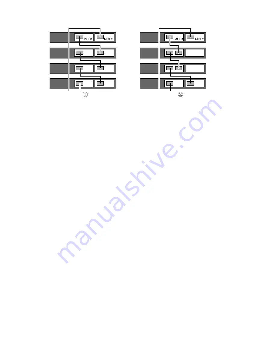
Figure 3-33 

Cable connections for a stack with 1-port interface modules 


Verifying the Installation 

z


Check whether the selected power is the same as the power label on the switch;  

z


Check whether the ground wire is connected;  

z


Check whether the power cords are connected correctly;  

z


Check whether all the interface cables are routed indoors. If there are cables outdoors, check that 
the socket strip with lightning protection and lightning arresters for network ports have been 
correctly connected. 


Содержание S5120-EI Series

Страница 1: ...H3C S5120 EI Series Ethernet Switches Installation Manual Hangzhou H3C Technologies Co Ltd Manual Version 5PW100 20090630...

Страница 2: ...oint SecEngine SecPath Comware Secware Storware NQA VVG V2 G Vn G PSPT XGbus N Bus TiGem InnoVision and HUASAN are trademarks of Hangzhou H3C Technologies Co Ltd All other trademarks that may be menti...

Страница 3: ...on and initialization of system files and so on 5 Boot ROM and Host Software Loading Introduces how to load Boot ROM and host software for an S5120 EI series switch 6 Maintenance and Troubleshooting...

Страница 4: ...stallation configuration and maintenance Technical Support Document Software Download Provides the documentation released with the software version Technical Support customer_service h3c com http www...

Страница 5: ...h3cnetworks com Warranty and other service benefits start from the date of purchase so it is important to register your product quickly to ensure you get full use of the warranty and other service ben...

Страница 6: ...us LED 1 15 Optional Interface Modules 1 15 Short haul Dual Port 10 GE CX4 Interface Module 1 16 Dual Port 10 GE SFP Interface Module 1 17 Dual Port 10 GE XFP Interface Module 1 18 One port 10 GE XFP...

Страница 7: ...for the Switch Stack 3 21 Verifying the Installation 3 24 4 Starting and Configuring the Switch 4 1 Setting up the Configuration Environment 4 1 Connecting the Console Cable 4 1 Console Cable 4 1 Con...

Страница 8: ...iii Configuration System Failure 6 4...

Страница 9: ...5120 52C PWR EI Physical dimensions H W D 43 6 440 300 mm 1 72 17 32 11 81 in 43 6 440 420 mm 1 72 17 32 16 54 in Weight 4 4 kg 9 70 lb 4 7 kg 10 36 lb 6 9 kg 15 21 lb 7 4 kg 16 31 lb Management port...

Страница 10: ...power consumption and 370 W of PoE power 920 W when RPS is connected with 180 W of system power consumption and 740 W of PoE power Cooling system Four fans for heat dissipation Six fans for heat diss...

Страница 11: ...0 28C EI Ethernet switch 1 AC power input 2 RPS power input shipped with a protective cover 3 Grounding screw 4 Interface module slot 1 MOD1 5 Interface module slot 2 MOD2 The S5120 28C EI provides tw...

Страница 12: ...S5120 52C EI Ethernet switch 1 AC power input 2 RPS power input shipped with a protective cover 3 Grounding screw 4 Interface module slot 1 MOD1 5 Interface module slot 2 MOD2 The S5120 52C EI provid...

Страница 13: ...e 1 6 Rear panel of the S5120 28C PWR EI Ethernet switch 1 RPS power input 2 AC power input 3 Grounding screw 4 Interface module slot 1 MOD1 5 Interface module slot 2 MOD2 The S5120 28C PWR EI provide...

Страница 14: ...Rear panel of the S5120 52C PWR EI Ethernet switch 1 RPS power input 2 AC power input 3 Grounding screw 4 Interface module slot 1 MOD1 5 Interface module slot 2 MOD2 The S5120 52C PWR EI provides two...

Страница 15: ...RPS status LED RPS 10 Port status LED mode switching button Rear Panel Figure 1 10 Rear panel of the S5120 24P EI Ethernet switch 1 AC power input 2 RPS power input shipped with a protective cover 3 G...

Страница 16: ...status LED Rear Panel Figure 1 12 Rear panel of the S5120 48P EI Ethernet switch 1 AC power input 2 RPS power input shipped with a protective cover 3 Grounding screw 4 DO NOT REMOVE label The S5120 48...

Страница 17: ...Transmission medium Category 5 unshielded twisted pair cable Standard IEEE 802 3i 802 3u 802 3ab 1000Base X SFP Port Each S5120 EI provides four 1000Base X SFP ports on its front panel You can select...

Страница 18: ...mbo port For each Combo port either the SFP port or the corresponding 10 100 1000Base T Ethernet port can be used at a time For details about the combo port mapping relationship please refer to Table...

Страница 19: ...Description Steady green The switch is started normally Flashing green 1 Hz The system is performing power on self test POST Steady red POST failed Flashing yellow 1 Hz POST on some ports failed PWR...

Страница 20: ...teady green Indicates port rate Flashing green 1 Hz supported by PoE switches only Indicates port PoE power supply Mode Steady yellow Indicates port duplex mode Seven Segment LED The seven segment LED...

Страница 21: ...WR EI or S5120 52C PWR EI that supports PoE can display the PoE power consumption percentage of the switch For details refer to Table 1 12 Table 1 12 Seven segment LED description 2 LED status LED Por...

Страница 22: ...so the port does not supply power Flashing yellow 3 Hz POST failed on the port Flashing green 1 Hz PoE mode supported by PoE switches only Off The port does not provide PoE power Steady green The port...

Страница 23: ...odules in Table 1 16 as needed The S5120 E1 series support IRF requiring physical connections between devices The 10 GE ports of the supported interface modules support IRF allowing you to connect the...

Страница 24: ...supports CX4 electrical and protocol standards Only H3C s CX4 power cables can be used for connecting the CX4 ports A CX4 cable is hot swappable and its maximum transmission distance is 3 m 9 84 ft w...

Страница 25: ...SFP transceivers and SFP cables refer to Table 1 18 Table 1 18 SFP transceivers and SFP cables supported by dual port 10 GE SFP interface module Transceiver Cable type Transceiver Cable Central wavele...

Страница 26: ...nd of SFP transceivers and SFP cables refer to H3C Low End Series Ethernet Switches Pluggable Modules Manual Dual Port 10 GE XFP Interface Module Figure 1 19 Dual port 10 GE XFP interface module Figur...

Страница 27: ...chnical support personnel to obtain the latest information about XFP transceivers z For specifications of XFP transceivers refer to H3C Low End Series Ethernet Switches Pluggable Module Manual One por...

Страница 28: ...1 20 Description of LEDs on interface modules LED Mark Status Description On The port is normally connected The LED blinks quickly when the port is sending or receiving data Port LED of an interface...

Страница 29: ...inlet exhaust vents for ventilation z The rack or workbench has a good ventilation system z The rack is sturdy enough to support the device and its accessories z The rack or workbench is well earthed...

Страница 30: ...0 05 Cl2 0 01 Electromagnetic Susceptibility The operation of your switch can be affected by external interferences such as conducted emission by capacitance coupling inductance coupling electromagnet...

Страница 31: ...o the laser beam produced by the fiber may hurt your eyes Installation Tools z Flathead screwdriver z Phillips screwdriver z ESD preventive wrist strap The installation tools are not shipped with the...

Страница 32: ...bear any consequence resulted from your actions without permission Installation Flow of the Switch Figure 3 1 Hardware installation flow of the switch Start Install the switch to the specified positio...

Страница 33: ...ray z Use front mounting brackets and rear mounting brackets z Use front mounting brackets and guide rails The installation methods of a switch depend on the depth and width of the switch For the spec...

Страница 34: ...fix the mounting bracket to the cabinet Use one M6 screw For the selection of front and rear mounting brackets see Table 3 2 Table 3 2 Selection of mounting bracket for S5120 EI Series Ethernet switch...

Страница 35: ...y only to standard cabinets 1 000 mm 39 37 in deep Use other supports to substitute for guide rails in the case of other cabinet depths Use Front Mounting Brackets to Install a Switch Only the S5120 2...

Страница 36: ...Brackets and a Tray to Install a Switch All models of the S5120 EI series support installation using front mounting brackets together with a tray Follow these steps to install a switch into a 19 inch...

Страница 37: ...ackets and fix one end of mounting brackets to the switch as shown in Figure 3 5 Step4 Take out the load bearing screws packed together with the rear mounting brackets and place them in a proper posit...

Страница 38: ...e 3 9 Figure 3 9 Fix front and rear mounting brackets 1 1 7 3 4 5 6 2 1 Front square holed post 2 Load bearing screw Used to bear the weight 3 Rear panel 4 Rear square holed post 5 Rear mounting brack...

Страница 39: ...nel 2 Rear square holed post 3 Load bearing screw 4 Rear mounting bracket Step7 Fix the other end of the front mounting brackets to the front brackets with screws and captive nuts and ensure that fron...

Страница 40: ...llation using front mounting brackets together with guide rails Follow these steps to install a switch into a 19 inch standard cabinet Step1 Wear an ESD preventive wrist strap and ensure a good skin c...

Страница 41: ...ure that the bottom side of the guide rails and the switch are in close contact Figure 3 13 Install front mounting brackets and guide rails 1 Front panel Step6 Fix the other end of front mounting brac...

Страница 42: ...t dissipation z Do not place heavy objects on your switch z In the case of stack application the vertical distance between two switches must be at least 1 5 cm 0 59 in Connecting the Grounding Cable z...

Страница 43: ...2 Grounding sign 3 Grounding hole 4 OT terminal 5 PGND cable 6 Grounding screw To attach the other end of the PGND cable to the grounding strip in the equipment room follow these steps Step1 Cut the...

Страница 44: ...hould have a dimension no less than 50 50 5 mm 1 97 1 97 0 20 in and the steel tube should have a wall thickness no less than 3 5 mm 0 14 in and be zinc coated Weld the yellow green ground wire to the...

Страница 45: ...that the ground wire has been properly connected before powering on the switch Connecting the AC Power Cord To connect an AC power cord follow these steps Step1 Connect one end of the chassis ground...

Страница 46: ...the switch is ON If the LED is ON it shows the power cord is properly connected Figure 3 19 Connect an AC power cord to a horizontal AC power socket 1 Figure 3 20 Connect an AC power cord to a horizo...

Страница 47: ...DC receptacle see callout 1 in Figure 3 24 If you plug it with the upside down the insertion is not smooth because of the specific structure design of the RPS DC receptacle and the RPS plug Step4 Use...

Страница 48: ...120 52C EI S5120 24P EI S5120 48P EI switch provides two interface module slots on the rear panel For details about optional interface modules refer to Optional Interface Modules on page 1 15 The inst...

Страница 49: ...reventive wrist strap is properly grounded Step2 Use a Phillips screwdriver to loosen the captive screws at both sides of the interface module until all spring pressure is released Step3 Pull the inte...

Страница 50: ...Removing Dedicated CX4 SFP Cable Step1 Put on an ESD preventive wrist strap and verify the ESD preventive wrist strap properly grounded Step2 Hold the plug of the SFP cable pull the handle at the end...

Страница 51: ...Task Remarks 1 Draw a plan for the switch stack Take the following into consideration z Number of stack members and the bandwidth z Interface modules and cables z Stacking mode ring or link stack z C...

Страница 52: ...ration Determine the number of stack members and the bandwidth You can determine the number of stack members and the bandwidth according to the network scale z The S5120 EI series support two to four...

Страница 53: ...face modules on such devices Connect the cables Before connecting the cables determine the actual position of the member devices and the length of the cables and observe the following z Understand the...

Страница 54: ...ations of the ports of the interface modules are not limited Figure 3 32 Cable connections in a switch stack system in the aggregation mode z 1 port interface modules do not support port aggregation W...

Страница 55: ...as the power label on the switch z Check whether the ground wire is connected z Check whether the power cords are connected correctly z Check whether all the interface cables are routed indoors If th...

Страница 56: ...m for configuration environment setup Connecting the Console Cable Console Cable A console cable is an 8 core shielded cable One end of the cable is a crimped RJ 45 connector which is connected to the...

Страница 57: ...the switch z When disconnecting a PC from a powered on switch you are recommended to disconnect the DB 9 connector of the console cable from the PC after disconnecting the RJ 45 connector from the swi...

Страница 58: ...nter the HyperTerminal window The Connection Description dialog box appears as shown below Figure 4 3 Connection description of the HyperTerminal Step2 Type the name of the new connection in the Name...

Страница 59: ...t Bits per second to 9600 Data bits to 8 Parity to None Stop bits to 1 and Flow control to None Figure 4 5 Set the serial port parameters Step4 Click OK after setting the serial port parameters and th...

Страница 60: ...y that z The power cord and ground cable are properly connected z The power supply voltage is consistent with that required by the switch z The console cable is properly connected the terminal which c...

Страница 61: ...conds For the setting of the startup mode refer to the next section z If you press Ctrl B within 1 second the system displays Password Enter the correct Boot ROM password and click Enter to enter the...

Страница 62: ...he Boot ROM password 9 Set switch startup mode Set the startup mode of the switch 0 Reboot Restart the switch z If you perform no operation or press a key other than Ctrl B within one second Once the...

Страница 63: ...0 9 Enter 9 and the system prompts you to change the startup mode The current mode is fast startup mode Are you sure you want to change it to full startup mode Yes or No Y N Enter Y The system displa...

Страница 64: ...he Boot Menu is displayed If you press Ctrl B within five seconds the Boot Menu is displayed If you perform no operation or press a key other than Ctrl B within five seconds the system begins to autom...

Страница 65: ...Enter The following prompt is displayed H3C You can configure the switch now The H3C Series switches provide abundant command views For detailed descriptions about the configuration commands and CLI r...

Страница 66: ...ftware on the switch Approach Section Loading Software Using XMODEM Through Console Port Loading Software Using TFTP through Ethernet Port Loading files through the Boot ROM menu Loading Software Usin...

Страница 67: ...the program and if you want to enter the Boot Menu at this time you will have to restart the switch Input the correct Boot ROM password by default no password is set on the switch and you can click En...

Страница 68: ...eceiving program sends an acknowledgement packet and the sending program proceeds to send another packet otherwise the receiving program sends a negative acknowledgement packet and the sending program...

Страница 69: ...1 9600 2 19200 3 38400 4 57600 5 115200 0 Return Enter your choice 0 5 3 Set the download rate of the console port on the switch Select an appropriate download rate For example if you select 115200 bp...

Страница 70: ...tch Step1 Select Call Disconnect in the HyperTerminal window to disconnect the terminal from the switch Figure 5 1 Disconnect the terminal from the switch Step2 Select File Properties In the Propertie...

Страница 71: ...ction The new settings can take effect only after you reestablish the connection 5 Download the Boot ROM file Step1 Press Enter in the HyperTerminal window to start downloading the program The system...

Страница 72: ...ure 5 6 Page for file sending After the Boot ROM file is downloaded the terminal displays the following information CCCCCCCCCCCCCCCCCCCCCCCCCCCCCCCCCCdone Bootrom updating done Your baudrate should be...

Страница 73: ...estart the device After that the updated Boot ROM file becomes effective Loading host software Step 1 Select 1 in Boot Menu to load the host software of the switch The system displays the following in...

Страница 74: ...emulation program on the configuration PC Start the switch Then enter the Boot Menu At the prompt Enter your choice 0 9 select 6 in the Boot Menu and then press Enter to enter the Boot ROM update menu...

Страница 75: ...are Select 1 in Boot Menu to load the host software of the switch The system displays the following information 1 Set TFTP protocol parameter 2 Set FTP protocol parameter 3 Set XMODEM protocol paramet...

Страница 76: ...nu and then press Enter to enter the Boot ROM update menu shown below Bootrom update menu 1 Set TFTP protocol parameter 2 Set FTP protocol parameter 3 Set XMODEM protocol parameter 0 Return to boot me...

Страница 77: ...arameter 2 Set FTP protocol parameter 3 Set XMODEM protocol parameter 0 Return to boot menu Enter your choice 0 3 2 To load the host software through FTP select 2 The subsequent steps are almost the s...

Страница 78: ...y Updating BootRom please wait Upgrade Bootrom succeeded Step3 Update the host software on the switch H3C boot loader file S5120 EI bin H3C display boot loader The current boot app is flash S5120 EI b...

Страница 79: ...ownloading z Power interruption is not allowed during software loading Loading Software Using TFTP The remote loading by using TFTP is similar to the remote loading by using FTP The only difference is...

Страница 80: ...f the software to be loaded and the correct working path of TFTP server when using FTP verify that you have specified the correct server and switch IP addresses the correct name of the software to be...

Страница 81: ...s LED is off an AC input failure occurs Then do the following z Check whether the AC power cord is well connected to the switch whether the AC receptacle on the switch and the AC power socket are faul...

Страница 82: ...ollowing z Check whether the AC power cord is well connected to the switch whether the AC receptacle on the switch and the AC power socket are faulty z Check whether the AC external power supply syste...

Страница 83: ...configuration terminal or the displayed characters will be totally illegible Troubleshooting when there is no terminal display If there is no output information after the configuration is powered on...

Страница 84: ...Safety Manual B 1 Regulatory Compliance Information B 1 Regulatory compliance standards B 1 European Directives compliance B 1 USA regulatory compliance B 2 Canada regulatory compliance B 2 Japan regu...

Страница 85: ...u can use cable clips and screws to fasten the lightning arrester for AC power on the cabinet workbench or the wall of equipment room Figure A 1 Diagram of lightning arrester 1 Working LED green On me...

Страница 86: ...und wire of the arrester is not well grounded or because the live and zero wires are connected in reverse direction You may check that in the following way When the red LED is on use a multimeter to e...

Страница 87: ...A CISPR 22 CLASS A EN 55022 CLASS A AS NZS CISPR22 CLASS A CISPR 24 EN 55024 EN 61000 3 2 EN 61000 3 3 EN 61000 6 1 ETSI EN 300 386 GB 9254 YD T993 Safety UL 60950 1 CAN CSA C22 2 No 60950 1 IEC 6095...

Страница 88: ...or such interference problem and the expenses incurred therefrom shall be covered by the customers This equipment has been tested and found to comply with the limits for a Class A digital device pursu...

Страница 89: ...ic environment radio disturbance may arise When such trouble occurs the user may be required to take corrective actions CCC S5120 24P EI S5120 48P EI GB9254 Class A YD T993 GB4943 A Safety Information...

Страница 90: ...ipment installation and maintenance z Lesen Sie bitte alle Arbeitsanweisungen und Sicherheitvorschriften sorgf ltig durch bevor Sie mit dem Arbeiten beginnen Nur durch Beachtung dieser Hinweise l sst...

Страница 91: ...description Sicherheitssymbole und Beschreibung Safety Symbol Symbole Description Erl uterung Generic alarm symbol To suggest a general safety concern Alarm Hinweis auf ein generelles Sicherheitsprob...

Страница 92: ...before operation permanently And the cross section of protective earthing conductor shall be at least 1mm2 z Das System muss vor der st ndigen Inbetriebnahme geerdet werden Der Querschnitt der Erdver...

Страница 93: ...t via damp objects with high voltage and AC mains supply may result in fatal danger Die Hochspannungsleitungen stellen f r die Arbeit der Ausr stung erforderliche Energie zur Verf gung Direkter oder i...

Страница 94: ...e AC cable bridging and wiring through a certain area must follow the local rules and regulations The personnel who perform high voltage operations should be qualified for high voltage and AC operatio...

Страница 95: ...werden bevor die Zuleitung angebracht oder entfernt wird z z Before the power cable is connected it must be confirmed that the power cable and label comply with the requirements of the actual installa...

Страница 96: ...g durch Blitzschlag zu sch tzen ist eine ordnungsgem e Erdung erforderlich AC Laser Laser The laser hazard level of this equipment is Class 1 Die von diesem Laser ausgehende Gefahr entspricht der Kate...

Отзывы: