


47
2.
Loosen the fastening screw on the wiring terminal marked with RTN(+) with an M6 wrench, and
remove the screw, spring washer, and flat washer.
3.
Connect one end of the black DC power cord marked with "–" to the RTN(+) terminal on the power
supply, install the flat washer, spring washer, and fasten the screw.
4.
Connect one end of the blue DC power cord marked with "–" to the negative terminal (–) on the
power supply; connect the "–" end of the grounding cable to the terminal marked with PE on the
rightmost of the grounding strip.
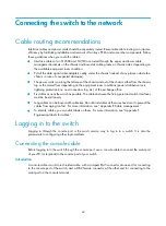
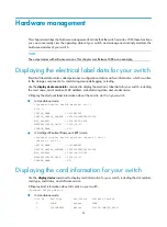
Figure 46
Connecting the DC power cord to the grounding strip
5.
Connect the other end of the DC power cord to the power source:
a.
Connect the other end of the black DC power cord to the RTN (+) terminal that provides power
to the switch.
b.
Connect the other end of the blue DC power cord to the negative terminal (–) that provides a
power supply to the switch.
c.
Connect the other end of the grounding cable to a reliable grounding point.
6.
Put the protection cover on the wiring terminals.
1
2
3
4
Содержание S12500 Series
Страница 40: ...30 Figure 28 Installing an upper expansion cable management bracket 1 2 3 4 5 6 7...
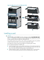
Страница 109: ...99 Figure 74 Replacing a card for the S12504 A Card to be removed B Card to be installed...
Страница 149: ...139 Figure 85 Loopback operation on an optical transceiver...
Страница 164: ...154 Figure 100 Example of a device label...
Страница 167: ...157 Figure 104 Network cable management...


