


37
4.
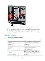
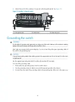
Attach the switch to the workbench or ground with L-shaped brackets. See
.
Figure 35
Installing L-shaped brackets
(1) L-shaped bracket
(2) Wall anchor
(3) Mounting screw
Grounding the switch
WARNING!
For the safety of operators and equipment, securely ground the switch. Make sure the resistance reading
between the switch chassis and the ground is less than 1 ohm.
Most racks are equipped with a grounding strip. You can connect the yellow-green grounding cable of
the switch to the grounding strip.
CAUTION:
Connect the grounding cable to the earthing system in the equipment room. Do not connect it to a fire main
or lightning rod.
Use the supplied grounding cable (CAT 6 cable with dual-hole OT terminals).
To connect the grounding cable:
1.
Remove the two grounding screws from the switch chassis.
2.
Use the grounding screws to attach one end of the grounding cable to the chassis.
3.
Connect the other end of the grounding cable to the grounding strip of the rack in the same way.
Содержание S12500 Series
Страница 40: ...30 Figure 28 Installing an upper expansion cable management bracket 1 2 3 4 5 6 7...
Страница 109: ...99 Figure 74 Replacing a card for the S12504 A Card to be removed B Card to be installed...
Страница 149: ...139 Figure 85 Loopback operation on an optical transceiver...
Страница 164: ...154 Figure 100 Example of a device label...
Страница 167: ...157 Figure 104 Network cable management...


