143
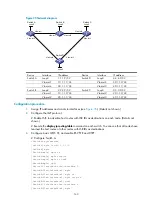
Figure 35
Network diagram
Device Interface IP
address
Device
Interface
IP address
Switch A
Loop0
1.1.1.9/32
Switch D
Loop0
4.4.4.9/32
Vlan-int1
10.1.1.1/24
Vlan-int4
30.1.1.2/24
Vlan-int4
30.1.1.1/24
Vlan-int3
40.1.1.1/24
Switch B
Loop0
2.2.2.9/32
Switch C
Loop0
3.3.3.9/32
Vlan-int1
10.1.1.2/24
Vlan-int2
20.1.1.2/24
Vlan-int2
20.1.1.1/24
Vlan-int3
40.1.1.2/24
Configuration procedure
1.
Assign IP addresses and masks to interfaces (see
). (Details not shown.)
2.
Configure the IGP protocol:
# Enable IS-IS to advertise host routes with LSR IDs as destinations on each node. (Details not
shown.)
# Execute the
display ip routing-table
command on each switch. You can see that all nodes have
learned the host routes of other nodes with LSR IDs as destinations.
3.
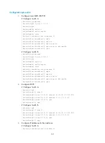
Configure basic MPLS TE, and enable RSVP-TE and CSPF:
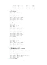
# Configure Switch A.
<SwitchA> system-view
[SwitchA] mpls lsr-id 1.1.1.9
[SwitchA] mpls
[SwitchA-mpls] mpls te
[SwitchA-mpls] mpls rsvp-te
[SwitchA-mpls] mpls te cspf
[SwitchA-mpls] quit
[SwitchA] interface vlan-interface 1
[SwitchA-Vlan-interface1] mpls
[SwitchA-Vlan-interface1] mpls te
[SwitchA-Vlan-interface1] mpls rsvp-te
[SwitchA-Vlan-interface1] quit
[SwitchA] interface vlan-interface 4
[SwitchA-Vlan-interface4] mpls
Switch A
Loop0
Vlan-int1
Switch B
Switch C
Switch D
Loop0
Loop0
Vlan-int1
Vlan-int2
Vlan-int2
Vlan-int4
Vlan-int3
Vlan-int4
Vlan-int3
Loop0


