background image

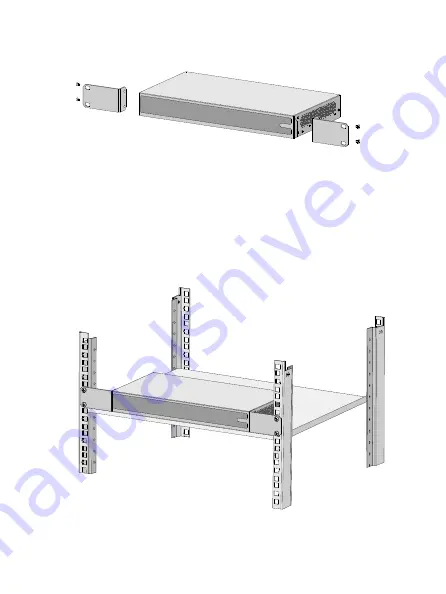
Figure 1 Attaching mounting brackets to the switch 


3. 

Place the switch on a rack shelf in the rack. Push the switch in 
until the oval holes in the brackets align with the mounting holes 
in the front rack posts. 

4. 

Use screws to secure the mounting brackets to the front rack 
posts. 

Figure 2 Mounting the switch in the rack 


Содержание Mini S9G

Страница 1: ...n a clean environment Dust buildup on the chassis might result in electrostatic adsorption which reduces lifespan of the device and can cause communication failure Keep the air inlet and outlet vents...

Страница 2: ...Workbench mounting Wall mounting S9G Not supported Supported Supported S26 Supported Supported Not supported S26G Supported Supported Not supported Mounting in a 19 inch rack No mounting brackets and...

Страница 3: ...the switch on a rack shelf in the rack Push the switch in until the oval holes in the brackets align with the mounting holes in the front rack posts 4 Use screws to secure the mounting brackets to th...

Страница 4: ...p and clean the four recessed areas in the chassis bottom with a soft and dry cloth 3 Attach the rubber feet to the recessed areas 4 Place the switch upside up on the workbench Mounting on a wall You...

Страница 5: ...or If you use screws and screw anchors of the recommended size the hole diameter is 5 mm 0 20 in 2 Drill two holes spacing 90 mm 3 54 in on the wall Make sure the two holes are on a horizontal line 3...

Страница 6: ...orrectly connecting the grounding cable is crucial to lightning protection and EMI protection The switch is not provided with a grounding cable Prepare one yourself The S9G switch does not have a grou...

Страница 7: ...her end of the cable 3 Remove the hex nut from a grounding post on the grounding strip Attach the loop to the grounding post and fasten the hex nut Figure 5 Connecting the grounding cable Connecting t...

Страница 8: ...ve an SFP transceiver module do not touch the golden plating on it Remove the dust plugs from an SFP transceiver module only when you are to connect optical fibers to the module Before installing an S...

Страница 9: ...nectors of the optical fibers to the transceiver module Figure 7 Installing the optical fibers Accessing the switch The switch supports Web management To access the switch 1 Connect the switch to a PC...

Страница 10: ...address bar of your browser 3 On the login page that opens enter the user name password and verification code select the language and click Login The default username and password are admin case sens...

Страница 11: ...11 Appendix A Chassis views and technical specifications Chassis views Front panel Figure 9 S9G front panel Figure 10 S26 front panel 1 2 3 4 5...

Страница 12: ...TX copper port status LED 4 1000Base X SFP fiber port status LED 5 100Base X SFP fiber port status LED 6 10 100Base TX copper port 7 10 100 1000Base T copper port 8 100 1000Base X SFP fiber port 9 Res...

Страница 13: ...t 5 seconds until the power LED slowly flashes green Restoring the factory default and rebooting the switch Press the reset button for about 10 seconds until the power LED fast flashes green If you pr...

Страница 14: ...tions Item S9G S26 S26G Dimensions H W D 27 235 105 mm 1 06 9 25 4 13 in 44 330 173 mm 1 73 12 99 6 81 in 44 330 173 mm 1 73 12 99 6 81 in Weight 0 5 kg 1 10 lb 1 5 kg 3 31 lb 1 6 kg 3 53 lb Port 8 10...

Страница 15: ...1 A AC 100 VAC to 240 VAC 50 Hz or 60 Hz Connector Fiber port LC Copper port RJ 45 Port transmission rate Fiber port 1000 100 Mbps full duplex Copper port Half full duplex auto negotiation MDI MDI X O...

Страница 16: ...pper port status LED on S26 and S26G switches Link Act Steady green A 1000 Mbps link is present Flashing green The port is receiving or sending data at 1000 Mbps Steady yellow A 10 100 Mbps link is pr...

Страница 17: ...low A 10 100 Mbps link is present Flashing yellow The port is receiving or sending data at 10 100 Mbps Off No link is present 100 1000 BASE X SFP port status LED Link Act Steady green A 1000 Mbps link...

Отзывы: