background image

-

 16 -

 | 

P a g e


Reverse Osmosis Membrane Replacement 

 
 RO versions (RO) 

(every three years)


a)


Use the same procedure as above sec a-c.  

b)


Remove the RO stage from the clips. Disconnect the white tubing 

from the RO housing cap.  


c)


Remove the cap from the housing by unscrewing it.  

d)


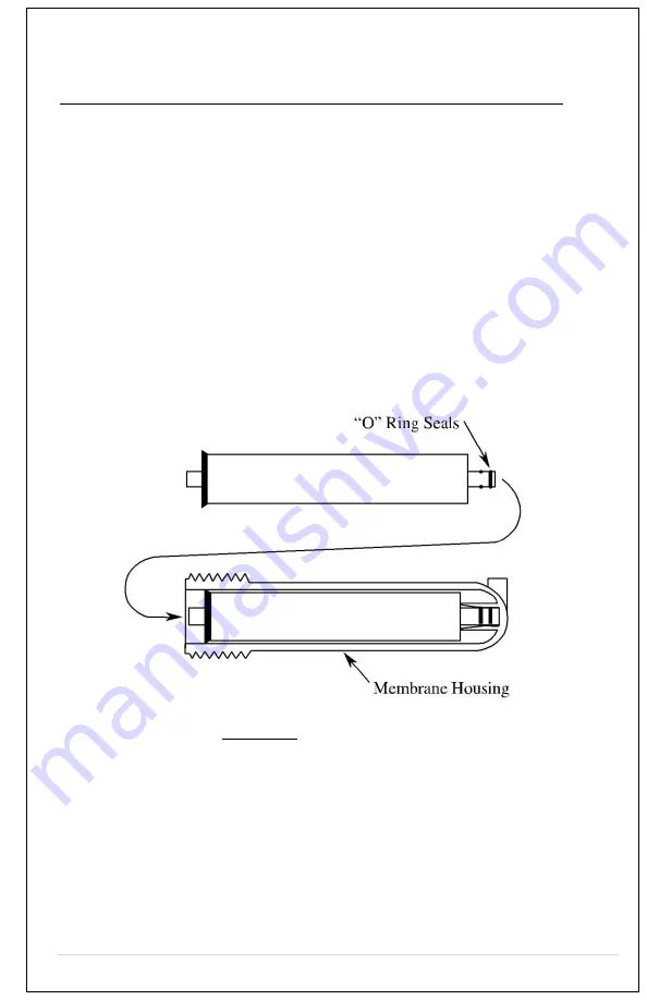
Using a pair of pliers, remove the RO element from the housing by 

grasping the tube end and pulling it out.  


e)


Use  RO  filter  replacement  P/N  GE50  (50gpd  GE  membrane). 

Insert  the  element  into  the  housing  with  double  “o”-ring  end 

going  in  first–toward  the  bottom  of  the  housing.  Make  sure  the 

“o”-rings are sealed. Replace the cap. Reconnect the white tubing. 

Proceed as in above sec-g.  


Figure. 8 

RO Membrane Installation 


Содержание FW-750

Страница 1: ... 1 P a g e Model H2O 750 FW 750 Operation Manual ...

Страница 2: ...nk Flush 14 Cleaning and Maintenance 15 Filter Replacement 16 Reverse Osmosis Membrane Replacement 17 Troubleshooting 18 Specifications 19 Warranty 19 List of Figures Figure 1 Assembly Drawing Model H2O 750 5 Figure 2 m Water Flow Chart H2O 750 6 7 Figure 4 Water Cooler Connections 9 Figure 5 Drain Connections for RO Models 11 Figure 6 Filter Configuration Model F 13 Figure 7 Back View of Coolers ...

Страница 3: ... around 44ºF and the hot water is heated at 180ºF All International H2O Inc models are manufactured and marked as RO or F assemblies The RO assembly utilizes Reverse Osmosis water purification technology that produces pure and safe water from city or well water The RO assembly is comprised of a 5 micron sediment filter a carbon GAC 10 micron filter RO membrane and a post carbon filter to improve t...

Страница 4: ...nothing is damaged or dislodged from shipping Description Model H2O 750 The Model H2O 750 provides water at two temperatures The water is dispensed from two spigots one hot and one cold The assembly drawing is shown in Figure 1 for the H2O 750 and Figure 2 for the H2O 1000 Water flows from the filter system into the top tank also known as the cold water tank This tank then feeds the hot tank that ...

Страница 5: ... 5 P a g e Figure 1 Assembly Drawing Model H2O 750 Water Production Flow Chart Model H2O 750 ...

Страница 6: ... 6 P a g e H2O 1000 Figure 3 Water Flow Chart ...

Страница 7: ...s cooler in an area were water may cause severe or costly damage 2 Do not position the cooler where it can be hit or bumped by vacuum cleaners or floor waxing machines This can cause breaks in the waterline connection fittings and compressor tubing Water Cooler Connections ...

Страница 8: ...aking all your connections To remove the tube sections see Figure 7 Disconnect The one quarter inch plastic tubing should be used for making the Feed Water and Drain connections If hard copper tubing is used for the Feed Water and Drain connections the bulkhead fittings must be changed to a metal fitting Figure 4 Water Cooler Connections Feed Water Connections ...

Страница 9: ...der the sink Attach the 1 4 inch tubing to the compression fitting on the side of the valve Clamp the saddle valve over copper or plastic feed line cold water only Turn the handle on the valve until the needle stem pierces the tube Then retract the needle one to two turns to start water flow See photo inset Drain Connection ...

Страница 10: ...n saddle on the drain pipe before the drain trap Allow proper space for the drilling operation Tighten the saddle bolts evenly on both sides Using the opening in the drain outlet saddle as a guide drill a one quarter inch 1 4 hole in the drain pipe Clean any debris out of the drain saddle connection Connect the drain line to the cooler using the 1 4 black tubing supplied Figure 5 Drain Connections...

Страница 11: ...be Fitting grips before it seals Ensure tube is pushed into the tube stop Push up to tube stop Push the tube into the fitting to the tube stop The collet gripper has stainless steel teeth that hold the tube firmly in position while the O ring provides a permanent leak proof seal Pull to check secure Pull on the tube to check it is secure It is good practice to test the system prior to leaving site...

Страница 12: ...Open ball valve inside the cooler 1 4 turn The handle in line with the tube is on Let water flow through filters into the bucket or pan to push out air and carbon fines When water runs clear turn off the ball valve and re connect the tube to the filter Turn the water on to the filter system by opening the ball valve inside the cooler 1 4 turn handle in line with tube is on Check all connections to...

Страница 13: ...UTION DO NOT TURN ON HOT OR COLD POWER CONTROLS YET Remove the top cover of the cooler by removing two screws from the back of the top cover Pull the cover off exposing the main tank This model uses an electric float valve to control flow to the tank The unit does have to be plugged in to start water flow Water will flow into the cold tank and then the hot tank as well Let cooler tanks fill with t...

Страница 14: ...ach Let stand for five to 10 minutes Drain the water then let water from filters refill tank and drain a second time Remember to drain from dispensing spigots also Note Upon completion of cleaning wait at least 10 minutes after the power cord is plugged in before turning on the Hot and Cold Water buttons ...

Страница 15: ...a TURN OFF POWER TO HOT COLD ELEMENTS b Swing open the front hinged cover c Close the ball valve to stop water flow through the filters d Place a towel under the filters to catch water The filters will have water in them which will run out when the filters are unlocked e Twist the filters to remove them from their housings f These filters are disposable encapsulated filters Remove and discard the ...

Страница 16: ... the housing by unscrewing it d Using a pair of pliers remove the RO element from the housing by grasping the tube end and pulling it out e Use RO filter replacement P N GE50 50gpd GE membrane Insert the element into the housing with double o ring end going in first toward the bottom of the housing Make sure the o rings are sealed Replace the cap Reconnect the white tubing Proceed as in above sec ...

Страница 17: ...ser Clean wire condenser every three months Place cooler in a well ventilated area Adjust thermostat Hot Water doesn t flow out of spigot Air may be trapped in the line Hold the spigot down for 30 seconds to relieve air Won t cool Controls not set Turn cold temperature switch on at back Panel not lit No power Check that the power cord is in the socket and turn on the cold hot buttons on the back o...

Страница 18: ...se within the condition of operation listed for a period of one year from the date of purchase The compressor has a 3 year warranty There is no liability assumed by the company for damage due to water leakage or other secondary effects from any component defect Labor is not covered in this warranty The warranty applies when Conditions of Operation below are met Conditions of Warranty Water System ...

Страница 19: ... 19 P a g e Your Trusted Vendor http www FilterWater com Tel 800 439 0263 Fax 215 354 0304 E mail Sales FilterWater com Mailing Address FilterWater com P O Box 968 Southampton PA 18966 USA ...

Страница 20: ...20 P a g e ...

Отзывы: