3. COMPONENT PARTS
CONTROL UNIT
The control unit collects and processes information from the pressure
sensor and the flow meter, and controls the motorised ball valve.
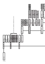
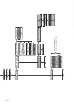
• The display shows the current status and menus.
• Turn and push the knob to navigate through the menu tree.
• The diode indicates status: green means normal operation and red
means alarm activated.
VALVE UNIT
The valve unit is installed on the building’s incoming tap water pipe and
consists of:
• A motorised ball valve for opening and closing the water supply. The
motorised ball valve can be operated manually by turning the mechani-
cal knob on the motor, or via the control unit. The position of the valve is
indicated by the red line in the viewing glass on the top of the motor.
• A pressure sensor that measures water pressure in the building’s tap
water system.
• A flow meter that continuously measures the water flow in the build-
ing’s tap water system.
COMMUNICATION CABLE
A standard network cable (RJ45) is used to connect the control unit to
the valve unit. The cable supplied is 3 metres long, but can be replaced
with a different cable of the desired length (max. 100 metres).
DC TRANSFORMER
Plug the adapter into a wall socket (230 V) and connect the low current
contact to the control unit (24 V).
9 (23)
ENGLISH
Содержание VATETTE
Страница 5: ...5 23 SVENSKA ...
Страница 27: ...5 23 ENGLISH ...
Страница 49: ...NORSK 5 23 ...
Страница 71: ...DANSK 5 23 ...
Страница 93: ...5 23 SUOMI ...
Страница 111: ......


