4
Band Saw Assembly and Installation
1. The saw may be attached to the worktable or a stand with 6 screws. .
2. The backplate rear end should be mounted on the end of the worktable or the stand so that band
saw can be tilted in the vertical position.
Saw Band Speed
Using the band saw, you should always select the speed most appropriate to the given material. A small
overview of adjusting various materials will give you the list of materials and cutting thereof.
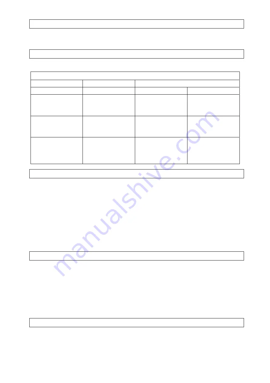
List of Materials and Cutting Thereof
Pulley to be used
Material
Speed
Motor
Saw
Tool steel
Stainless
Bearing bronze
20 m/min.
Small
Large
Regular steel
Hard brass
Bronze
29 m/min.
Medium-sized
Medium-sized
Soft brass
Aluminium
Other light-weight
materials
50 m/min.
Large
Small
Saw Band Replacement
Tilt the saw head into the vertical position, open the band cover and loosen the band clamping screw so
that the band may be removed from the wheels.
Fit in the new band as follows:
1. Put the saw band between the guide bearings.
2. Take the band with your left hand over the drive wheel (down) and hold it in the position.
3. Pull the band up with your right hand to get it closer to the drive wheel.
4. Pull with your left hand further at the saw band upper end
5. Set up the band adjusting screw with your right hand so that it is possible to shift it over the upper
wheel with your left hand.
6. Set up the band tension so that it cannot skid. The tension should not be excessive.
7. Put a couple of oil drops on the band.
8. Close the band cover.
Saw Upper Wheel Alignment
1. Remove the band cover.
2. Loosen the band clamping screw a bit so that the band is not tense at full.
3. Screw the socket screw on the clamping block for the upper wheel to be at precise parallel with the
drive wheel and the band is straight.
4. Put the band in correct tension.
5. Check on the band run so that you will switch the machine on .If the band is skidding forward, the
adjustment should be repeated until the band rear side is in contact with the upper wheel edge.
6. Switch the machine off again.
7. Remount the saw band cover.
Guide Bearings Set-up
Caution:
This is essential adjustment on the saw. . Reasonable result cannot be attained at work, if ht
guide bearing are not set up correctly. Clearance should not be above 0,1 mm or the saw band can be
in contact with the bearing. To set up in this way, the procedure should be as follows:
1. Each bearing should be fitted on an eccentric case and may be adjusted.
Содержание 40536
Страница 8: ...8 Technical Drawing...


