5
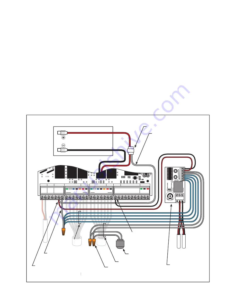
Connecting Light Kit to Mighty Mule FM500/502, GTO/PRO SW2500, SW3000,
and SW4000 Gate Openers:
1. Connect the RED wire from the Light Kit control board
and
a short section of 16 gauge low voltage wire (not
provided) to the RLY-COM (Relay Common) terminal on the gate opener control board. Connect the other end
of the short section of wire to the RED gate opener battery lead using the wire splicing locks provided.
See
diagram below and Figure 16
.
2. Connect the BLACK wire from the Light Kit control board to the COM (COMMON) terminal on the gate
operator control board.
See diagram below
.
3. Connect all the BLUE wires from the Light Kit control board together with a short section of 16 gauge low
voltage wire (no provided) using a wire nut (provided). Connect the other end of the short section of wire to the
NO (Normally Open) terminal RELAY OUT terminal on the gate opener control board.
See diagram below
.
4. Connect the WHITE wires from the photocell to the WHITE wires from the Light Kit control board using the
wire nuts provided.
See diagram below
.
x2
DELAY TIMER
0
60
SWITCH
18 VAC SOLAR RELAY OUT
~
~
-
+
NC
NO
RLY-COM
SLAVE INPUTS
GRN
WHT
BLUE
BRN
ORG
RED
BLK
MASTER INPUTS
GRN
WHT
BLUE
BRN
ORG
RED
BLK
GRN
BLK
RED
RECEIVER
COM
COM
CY
CL
E
CL
O
SE
SAFETY
EXIT
OPEN
SHADOW
LOOP
CL
O
SE
EDGE
OPEN
EDGE
STALL FORCE
MI
N
M
AX
J11
J8
J5
J13
J21
J6
J9
J2
J1
J12
Wires from
Lights
Photocell
Light Kit
Control Board
Wire Nuts
Wire Splicing Locks
Gate Opener Battery
BLACK Wire
to
COM
(common)Terminal
RED
Light Kit Wire and short sec-
tion of 16 gauge low voltage wire to
RLY-COM
on
RELAY OUT
Terminal
RELAY OUT
RELAY OUT
Mighty Mule 500/502, GTO/PRO SW2500, SW3000 and SW4000 Control Boards
BLUE
BLUE
BLUE
Wires
Wires
Wires
BLUE
BLUE
WHITE
Wires
WHITE
WHITE
Short section of 16 gauge low
voltage wire (any color) --
from
RLY-COM
terminal to
RED
battery lead.
Short section of 16 gauge
low voltage wire (any color)


