background image


203 

C

ONNEXIONS DU MODÈLE AVEC BY

-

PASS SÉPARÉ


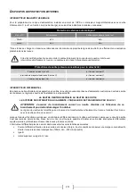
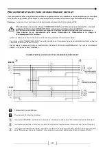
Le premier branchement à effectuer est celui du conducteur de protection (câble de terre), à relier à la 
borne marquée  PE. L'onduleur doit fonctionner branché à l’installation de terre. 


LE NEUTRE D’ENTRÉE ET DE BY-PASS DOIT TOUJOURS ETRE BRANCHES. 
LES LIGNES D’ENTRÉE ET DE BY-PASS DOIVENT SE REFERER AU MEME POTENTIEL DE NEUTRE.


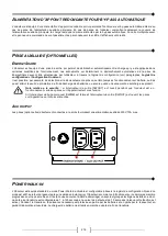
Brancher les câbles d'entrée et de sortie à la plaque à bornes


comme l’illustre la figure ci-dessous : 


Remarque 1

 : le branchement du conducteur de protection (câble de terre), doit être effectuée au moyen de l’anneau pour vis M6 


Remarque  2 :

  les branchements  au module  BATTERIE  ne  doivent être  effectués qu’en présence du  PACK  BATTERIES  (en 

option). 


P

ARCOURS DES CÂBLES 


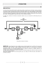
Nous conseillons de disposer les câbles de puissance en les faisant passer par derrière, sous l’UPS, vers la façade de l’appareil 
en les faisant remonter dans la zone des bornes comme indiqué dans la figure suivante: 


Dans la partie basse de la structure se trouvent par ailleurs des fentes pouvant être utilisées pour ancrer solidement les câbles 
à l’aide de colliers de dimensions adéquates.


Содержание SATURN

Страница 1: ...interruptible Power Supply SATURN 30 40 kVA Manuale d installazione ed uso Installation and use manual Installations und Bedienungsanleitung Manuel d installation et d utilisation Manual de instalacìon y uso ...

Страница 2: ......

Страница 3: ...n accordo con la normativa vigente In questo prodotto non sono utilizzati materiali pericolosi quali CFC HCFC o amianto Nella valutazione degli imballi la scelta del materiale è stata fatta prediligendo materie riciclabili Per il corretto smaltimento si prega di separare e di identificare la tipologia di materiale costituente l imballo seguendo la tabella sottostante Smaltire ogni materiale second...

Страница 4: ...AZIONE 18 IMMAGAZZINAMENTO DELL UPS 18 PREDISPOSIZIONE ALL INSTALLAZIONE 18 INFORMAZIONI PRELIMINARI 18 COMPATIBILITÀ ELETTROMAGNETICA 19 AMBIENTE D INSTALLAZIONE 19 BATTERIE INTERNE 20 RIMOZIONE DELL UPS DAL PALLET 21 CONTROLLO PRELIMINARE DEL CONTENUTO 22 POSIZIONAMENTO DELL UPS 22 OPERAZIONI PER L ACCESSO AI MORSETTI DELL UPS 22 COLLEGAMENTI ELETTRICI 23 SCHEMI DI CONNESSIONE ALL IMPIANTO ELETT...

Страница 5: ...SPLAY GRAFICO 38 MENU DISPLAY 40 MODALITÀ DI FUNZIONAMENTO 41 BYPASS PER MANUTENZIONE SWMB 41 ALIMENTATORE AUSILIARIO RIDONDANTE PER BYPASS AUTOMATICO 42 PRESE AUSILIARIE OPZIONALI 42 ENERGYSHARE 42 AUX OUTPUT 42 POWER WALK IN 42 DECLASSAMENTO DELLA POTENZA PER CARICHI 200 208V FASE NEUTRO 43 CONFIGURAZIONE UPS 43 PORTE DI COMUNICAZIONE 46 CONNETTORI RS232 E USB 46 COMMUNICATION SLOT 46 PORTA AS40...

Страница 6: ... garantisce bassa distorsione d ingresso fattore di potenza prossimo a uno e massima compatibilità con il gruppo elettrogeno BATTERY CARE SYSTEM permette la gestione personalizzata delle batterie per le diverse topologie e il monitoraggio continuo delle stesse aumentandone così l efficienza e la durata SMART INVERTER garantisce un efficienza straordinaria anche a basse percentuali di carico nonché...

Страница 7: ...7 VISTE ANTERIORI UPS Pannello di controllo con display grafico Ruote per la movimentazione dell UPS Porta frontale con serratura Piedino Griglia di aerazione ...

Страница 8: ...tore di bypass manuale Sezionatore di uscita Da sinistra Pulsante per partenza da batteria COLD START sopra Connettore R E P O Remote Emergency Power Off Porta contatti per AS400 Porta comunicazione USB Porta comunicazione RS232 Pannello copri morsetti Sezionatore porta fusibili di batteria Alloggiamento scheda parallelo opzionale ...

Страница 9: ...ioni di potenza BATTERIA ESTERNA INGRESSO BYPASS SEPARATO opzionale USCITA Connessione per segnale di sincronismo esterno Connessione per comando bypass di manutenzione remoto Connessione per sonda di temperatura esterna Battery Box ...

Страница 10: ...10 VISTA POSTERIORE UPS Alloggiamento per scheda relè di potenza opzionale Ventole schede di potenza Prese EnergyShare Aux Output 10A max e relativa protezione opzionale Ventola carica batterie ...

Страница 11: ...ionamento da batteria con preallarme di fine scarica o shutdown imminente Lampeggiante in Stand by funzione di riaccensione programmata attiva e rete assente LED carico su bypass Acceso fisso carico alimentato da linea bypass LED stand by allarme Acceso fisso allarme presente Lampeggiante stato di Stand by LED batterie da sostituire Acceso fisso batterie da sostituire Lampeggiante allarme batterie...

Страница 12: ...rasformatore è collegato ai morsetti di uscita dell UPS pertanto i valori riportati a display si riferiscono alle grandezze misurate a monte del trasformatore La presenza del trasformatore all interno dell UPS modifica il regime di neutro dell impianto L eventuale installazione di un bypass di manutenzione remoto in parallelo all UPS risulta incompatibile con la presenza del trasformatore Qualora ...

Страница 13: ...rotezioni di uscita valori consigliati per la selettività Fusibili normali gL gG In Corrente nominale 7 Interruttori magnetotermici Curva C In Corrente nominale 7 Fusibili ultrarapidi GF In Corrente nominale 3 DIFFERENZIALE IL NEUTRO D INGRESSO E COLLEGATO AL NEUTRO D USCITA IL SISTEMA DI DISTRIBUZIONE CHE ALIMENTA L UPS NON È MODIFICATO DALL UPS ATTENZIONE assicurare il corretto collegamento al n...

Страница 14: ...ssima pari a 10 metri La lunghezza massima dei cavi di collegamento al Battery Box opzionale è di 3 metri Nota la sezione massima dei cavi che si può inserire nella morsettiera è pari a 50 mmq morsetti di terra 70 mmq altri morsetti CONNESSIONI La prima connessione da effettuare e quella del conduttore di protezione cavo di terra da collegare alla vite siglata PE L UPS deve funzionare con il colle...

Страница 15: ... 1 sec Corrente di spunto 10 In STADIO DI USCITA Tensione Nominale 2 208 220 228 Vac Trifase con neutro 4wire Frequenza Nominale 3 50 60Hz Potenza apparente nominale in uscita 30kVA 40kVA Potenza attiva nominale in uscita 27Kw 36kW Fattore di potenza in uscita 0 9 Corrente di cortocircuito 1 5 x In per t 500ms Precisione della tensione in uscita riferita a tensione uscita 220Vac 1 Stabilità static...

Страница 16: ...o periodo di esercizio 3 Se la frequenza di rete è entro 5 del valore selezionato l UPS è sincronizzato con la rete Se la frequenza è fuori tolleranza o in funzionamento da batteria la frequenza è quella selezionata 0 01 4 Rete Batteria carico 0 100 5 Rete batteria rete carico resistivo 0 100 0 6 La corrente di ricarica viene regolata automaticamente in funzione della capacità della batteria insta...

Страница 17: ...collegamento all impianto di terra IL NEUTRO DI INGRESSO DEVE SEMPRE ESSERE COLLEGATO Collegare i cavi d ingresso e d uscita alla morsettiera come indicato nella figura sottostante Nota le connessioni al modulo BATTERIA devono essere effettuate solo se presente il Battery Box vedi paragrafo Connessioni UPS al Battery Box opzionale ...

Страница 18: ...9 e con batteria in tampone 1 1 28 kW 1101 kcal h 4368 B T U h 1 5 kW 1290 kcal h 5120 B T U h Potenza dissipata a carico nominale distorcente pf 0 7 e con batteria carica 1 1 02 kW 877 kcal h 3481 B T U h 1 35 kW 1160 kcal h 4605 B T U h Locale di installazione portata ventilatori per asportare calore 2 750mc h 800 mc h Corrente dispersa verso terra 3 50 mA Grado di protezione IP20 Ingresso cavi ...

Страница 19: ...are che la temperatura ambiente con UPS funzionante si mantenga tra 0 e 40 C L UPS è in grado di funzionare con una temperatura ambiente compresa tra 0 e 40 C La temperatura consigliata di funzionamento dell UPS e delle batterie è compresa tra 20 e 25 C Se infatti la vita operativa delle batterie è mediamente di 5 anni con una temperatura di funzionamento di 20 C portando la temperatura operativa ...

Страница 20: ...ll UPS Non aprire i portafusibili di batteria quando l ups alimenta il carico in funzionamento da batteria L interruzione della DC di batteria può causare un arco elettrico determinando rotture all apparecchiatura e o incendio Inoltre in mancanza di rete l energia per alimentare il carico è fornita dalle batterie pertanto l apertura delle protezioni di batteria porterebbe allo spegnimento del cari...

Страница 21: ...sano l UPS al pallet svitando le viti di tipo A e B Le staffe tolte precedentemente servono anche da scivoli Fissare gli scivoli al pallet utilizzando le viti di tipo A e facendo attenzione di allinearli in corrispondenza delle ruote Avvitare il piedino fino in fondo in modo da distanziarlo il più possibile dal piano del pallet Assicurarsi che la porta sia ben chiusa ATTENZIONE si raccomanda di fa...

Страница 22: ...almeno 30 cm dalla parete per un corretto deflusso dell aria soffiata dalle ventole di aerazione sulla parte superiore non dovranno essere appoggiati oggetti Terminato il posizionamento bloccare l apparecchiatura tramite l apposito piedino vedi Vista anteriore UPS In zone sismiche o su sistemi mobili è possibile riutilizzare le staffe di fissaggio al pallet scivoli per ancorare l UPS al pavimento ...

Страница 23: ... terra di protezione di tipo TT TN o IT è pertanto necessario rispettare la rotazione delle fasi Sono disponibili TRANSFORMER BOX opzionali per convertire gli impianti di distribuzione da 3 fili a 4 fili SCHEMI DI CONNESSIONE ALL IMPIANTO ELETTRICO UPS senza variazione di regime di neutro UPS con isolamento galvanico in ingresso UPS con isolamento galvanico in uscita ...

Страница 24: ...senza variazione di regime di neutro e con ingresso bypass separato UPS con isolamento galvanico in ingresso e con ingresso bypass separato UPS con isolamento galvanico in uscita e con ingresso bypass separato ...

Страница 25: ...ranno essere riferiti allo stesso potenziale Qualora le due alimentazioni fossero differenti è necessario utilizzare un trasformatore di isolamento su uno degli ingressi UPS senza variazione di regime di neutro e con ingresso bypass separato connesso su linea di alimentazione indipendente UPS con ingresso di bypass separato connesso su linea di alimentazione indipendente e con isolamento galvanico...

Страница 26: ...dello stato di funzionamento del gruppo nell istante di guasto si distinguono i due differenti casi UPS in FUNZIONAMENTO NORMALE il carico è commutato istantaneamente su linea di bypass UPS 30kVA I2t 20000A2s UPS 40kVA I2t 25000A2s la linea d ingresso è collegata all uscita senza nessuna protezione interna in blocco dopo t 0 5s UPS in FUNZIONAMENTO DA BATTERIA l UPS si auto protegge erogando in us...

Страница 27: ... ingresso il neutro proveniente dalla rete d alimentazione è collegato al neutro d uscita dell UPS non viene modificato il regime di neutro dell impianto IL NEUTRO D INGRESSO E COLLEGATO AL NEUTRO D USCITA IL SISTEMA DI DISTRIBUZIONE CHE ALIMENTA L UPS NON È MODIFICATO DALL UPS ATTENZIONE assicurare il corretto collegamento al neutro di ingresso perché la mancanza di questo potrebbe danneggiare l ...

Страница 28: ...massima dei cavi che si può inserire nella morsettiera è pari a 25 mmq per cavi flessibili 35 mmq per cavi rigidi CONNESSIONI Per UPS con bypass separato vedi paragrafo successivo La prima connessione da effettuare e quella del conduttore di protezione cavo di terra da collegare alla vite siglata PE L UPS deve funzionare con il collegamento all impianto di terra IL NEUTRO DI INGRESSO DEVE SEMPRE E...

Страница 29: ...iera come indicato nella figura sottostante Nota 1 la connessione del conduttore di protezione cavo di terra va effettuata tramite terminale occhiello per vite M6 Nota 2 le connessioni al modulo BATTERIA devono essere effettuate solo se presente il Battery Box opzionale INSTRADAMENTO DEI CAVI Si consiglia di cablare i cavi di potenza instradandoli dal retro sotto l UPS verso il fronte della macchi...

Страница 30: ...i porta nello stato di stand by vedi sezione UTILIZZO disalimentando completamente il carico Il circuito di R E P O é autoalimentato con circuiti di tipo SELV Non è richiesta quindi una tensione esterna di alimentazione Quando è chiuso condizione normale circola una corrente di 15mA max EXTERNAL SYNC Questo ingresso non isolato è utilizzabile per sincronizzare l uscita inverter con un segnale oppo...

Страница 31: ...ll alimentazione al carico e il danneggiamento dell UPS Usare cavi di sezione conforme a quanto riportato in Sezione dei cavi Per collegare il morsetto SERVICE BYPASS al contatto ausiliario del sezionatore bypass di manutenzione remoto usare cavo doppio isolamento di sezione 1mmq Nel caso l UPS sia collegato ad un trasformatore d isolamento verificare la compatibilità fra bypass manutenzione remot...

Страница 32: ...NTE assicurarsi di aver aperto i portafusibili SWBATT dell UPS e del Battery Box Prima di effettuare qualsiasi collegamento leggere attentamente le indicazioni riportate sul manuale del Battery Box Collegare i cavi provenienti dal Battery Box alla morsettiera dell UPS vedi figura seguente rispettando le polarità La prima connessione da effettuare è quella del cavo di protezione elettrica giallo ve...

Страница 33: ...possono causare malfunzionamenti o rotture all apparecchiatura Per l eventuale installazione collegare il cavo contenuto nell apposito kit opzionale al connettore EXT T_BATT vedi Vista connessioni UPS seguendo le indicazioni riportate nel relativo manuale Dopo l installazione effettuare l abilitazione della funzione di misurazione della temperatura esterna tramite il software di configurazione SIN...

Страница 34: ...ppresentato lo schema a blocchi dell UPS e vengono descritte le singole parti che lo compongono Diagramma a blocchi dell UPS IMPORTANTE I nostri gruppi di continuità sono concepiti e realizzati per una lunga durata anche nelle condizioni di servizio più severe Si ricorda tuttavia che si tratta di apparecchiature elettriche di potenza e come tali necessitano di controlli periodici Inoltre alcuni co...

Страница 35: ...nto non conforme a quanto riportato nel paragrafo Connessione UPS al Battery Box opzionale potrebbero essersi danneggiati i fusibili di batteria e altre protezioni in questo caso chiamare l assistenza per evitare ulteriori danni all UPS Alla chiusura dei fusibili si può verificare un piccolo arco dovuto alla carica dei condensatori interni all UPS tale evento è normale e non causa malfunzionamenti...

Страница 36: ...settiera richiudere il pannello protettivo ripetere le operazioni preliminari indicate nella pagina precedente Premere il pulsante per entrare nel menu di accensione Alla richiesta di conferma selezionare SI premere per confermare ed attendere qualche secondo Verificare che l UPS si predisponga nello stato con carico è alimentato da inverter Aprire il sezionatore d ingresso SWIN ed attendere qualc...

Страница 37: ...il display Premere il pulsante per entrare nel menu di accensione Alla richiesta di conferma selezionare SI e premere nuovamente il pulsante per confermare Si accendono tutti i led attorno al display per 1 sec circa ed il buzzer inizia ad emettere un beep ogni 7 sec La sequenza di accensione termina quando l UPS si predispone nello stato funzionamento da batteria Nota se non viene eseguita la sequ...

Страница 38: ...r Battery Line Inverter Load Inverter Output Line Battery Charge Automatic Static Bypass Lo schema mostra lo stato dei tre moduli logici di potenza PFC Converter Inverter Automatic Static Bypass Ogni modulo può assumere uno dei seguenti stati Modulo Spento Modulo acceso in funzionamento normale Modulo in allarme o in blocco I seguenti simboli invece rappresentano il flusso di energia da e verso le...

Страница 39: ... Zona di visualizzazione dello stato di funzionamento dell UPS La prima riga è sempre attiva e visualizza costantemente lo stato dell UPS in quell istante La seconda si attiva solo in presenza di un eventuale errore e o guasto dell UPS e mostra il tipo di errore guasto riscontrato A destra ogni rispettiva riga visualizza il codice corrispondente all evento in corso FUNZIONE TASTI Zona divisa in qu...

Страница 40: ...40 MENU DISPLAY ...

Страница 41: ...hiusura dell UPS può causare danni sia all operatore che all apparecchiatura Qui di seguito vengono illustrate le operazioni da effettuare per eseguire la manutenzione dell apparecchiatura senza interruzione dell alimentazione al carico L UPS deve alimentare il carico attraverso l inverter o il bypass automatico con rete presente N B Se l UPS si trova in funzionamento da batteria l inserimento del...

Страница 42: ...e scarica delle batterie o ancora al verificarsi di un evento di sovraccarico Note sulla sicurezza con UPS acceso se il sezionatore di uscita SWOUT viene aperto entrambe le prese rimangono in tensione Se viene inserito il sezionatore di bypass manuale SWMB viene aperto il sezionatore d uscita SWOUT e spento l UPS entrambe le prese non sono più alimentate AUX OUTPUT Presa di uscita opzionale connes...

Страница 43: ...ntrollo Inglese Inglese Italiano Tedesco Francese Spagnolo Polacco Russo Cinese Tensione di uscita Tensione nominale di uscita fase neutro 230V 220V 230V 240V Allarme sonoro Modalità di funzionamento dell allarme sonoro Ridotta Normale Ridotta non suona per intervento momentaneo del bypass Modo funzionamento Modalità di funzionamento dell UPS On line On line Eco Smart active Stand by off Batteria ...

Страница 44: ...educed Modalità di funzionamento dell allarme sonoro Reduced EnergyShare off Modalità di funzionamento della presa ausiliaria Always connected Timer Accensione e spegnimento UPS programmato giornaliero Disabled Autonomy limitation Tempo massimo di funzionamento da batteria Disabled Maximum load Soglia utente di sovraccarico Disabled Bypass Synchronization speed Velocità di sincronizzazione dell in...

Страница 45: ...uenza stabilizzatori Operating with Batteries Battery low time Tempo rimanente di autonomia stimata per il preavviso di fine scarica 3 min Automatic battery test Intervallo di tempo per il test automatico delle batterie 40 ore Parallel common battery Sistema parallelo con batteria unica comune tra tutti gli UPS del sistema Disabled Internal battery capacity Capacità nominale delle batterie interne...

Страница 46: ... RS232 CONNETTORE USB PIN NOME TIPO SEGNALE PIN SEGNALE 1 IN 1 VBUS 2 TX OUT TX linea seriale 2 D 3 RX IN RX linea seriale 3 D 4 4 GND 5 GND POWER 6 OUT 7 8 15V POWER Alimentazione isolata 15V 5 80mA max 9 WKATX OUT Risveglia alimentatore ATX COMMUNICATION SLOT l UPS è fornito di due slot di espansione per schede di comunicazione accessorie che consentono all apparecchiatura di dialogare utilizzan...

Страница 47: ...e a funzionare da inverter Se il ponticello viene rimosso in mancanza di rete l UPS riprende il funzionamento da batteria 4 5 12 BATTERY LOW OUTPUT 1 Segnala che le batterie sono a fine scarica quando il contatto 5 12 è chiuso 1 6 13 14 BATTERY WORKING OUTPUT 2 Segnala che l UPS sta funzionando da batteria quando il contatto 6 14 è chiuso 1 9 10 LOCK OUTPUT 3 Quando il contatto è chiuso segnala ch...

Страница 48: ... quando l UPS commuta su bypass per compensare lo spunto di corrente dovuto all inserimento di un carico distorcente Suono C La segnalazione viene fatta quando l UPS passa in funzionamento da batteria prima della segnalazione di fine scarica suono D È possibile tacitare la segnalazione vedi paragrafo Display grafico Suono D La segnalazione viene effettuata in funzionamento da batteria quando si ra...

Страница 49: ...l PC tramite il cavo seriale in dotazione oppure collegare la porta USB dell UPS ad una porta USB del PC utilizzando un cavo standard USB Scaricare il software dal sito web www ups technet com selezionando il sistema operativo desiderato Seguire le istruzioni del programma di installazione Per informazioni più dettagliate sull installazione ed utilizzo consultare il manuale del software scaricabil...

Страница 50: ...ONE La mancanza di tale collegamento può danneggiare l UPS e o il carico Collegare la rete ai morsetti come indicato nel paragrafo Installazione IL SEZIONATORE DIETRO LA PORTA SWIN É APERTO Chiudere il sezionatore MANCANZA DELLA TENSIONE DI RETE BLACKOUT Verificare la presenza della tensione di rete elettrica Eventualmente eseguire la accensione da batteria per alimentare il carico INTERVENTO DELL...

Страница 51: ...ludere il bypass di manutenzione Se il problema permane contattare il centro assistenza più vicino LA FASE 1 PRESENTA UNA TENSIONE MOLTO MINORE DELLE ALTRE DUE FASI Aprire SWIN effettuare la accensione da batteria attendere la fine della sequenza e chiudere SWIN IL DISPLAY VISUALIZZA UNO O PIÙ DEI SEGUENTI CODICI F11 F14 F15 F16 F17 L06 L07 L08 L09 L14 L15 L16 L17 L18 L19 L20 L21 L22 INSERIMENTO D...

Страница 52: ...NO SCARICHE L UPS RIMANE IN ATTESA CHE LA TENSIONE DI BATTERIA SUPERI LA SOGLIA IMPOSTATA Attendere la ricarica delle batterie o forzare in modo manuale l accensione andando nel menù ACCENSIONE IL DISPLAY VISUALIZZA UNO O PIÙ DEI SEGUENTI CODICI F06 F07 F08 RELÈ DI INGRESSO BLOCCATO Azionare il bypass di manutenzione SWMB spegnere l UPS aprire SWIN e contattare il centro di assistenza più vicino I...

Страница 53: ...L UPS FERITOIE DI AERAZIONE OSTRUITE O TROPPO VICINE ALLE PARETI MALFUNZIONAMENTO DEL SENSORE DI TEMPERATURA O DEL SISTEMA DI RAFFREDDAMENTO DEL CARICABATTERIE Rimuovere la causa della sovratemperatura Aprire i sezionatori portafusibili di batteria SWBATT e attendere che la temperatura del dissipatore del caricabatterie diminuisca Richiudere i portafusibili di batteria Se il problema si ripresenta...

Страница 54: ... attiva S09 Pronto per accensione S10 UPS in blocco carico non alimentato S11 UPS in blocco carico su bypass S12 Stadio BOOST o caricabatterie in blocco carico non alimentato S13 Convertitore di frequenza carico alimentato da inverter Command indica la presenza di un comando attivo CODICE DESCRIZIONE C01 Comando remoto di spegnimento C02 Comando remoto carico su bypass C03 Comando remoto di accens...

Страница 55: ...ss fuori tolleranza A19 Picco di corrente elevato su uscita Fase1 A20 Picco di corrente elevato su uscita Fase2 A21 Picco di corrente elevato su uscita Fase3 A22 Carico su Fase1 della soglia utente impostata A23 Carico su Fase2 della soglia utente impostata A24 Carico su Fase3 della soglia utente impostata A25 Sezionatore d uscita aperto A26 Batterie ramo positivo assenti o fusibili di batteria ap...

Страница 56: ...delle fasi di bypass errato F14 Sinusoide Fase1 inverter deformata F15 Sinusoide Fase2 inverter deformata F16 Sinusoide Fase3 inverter deformata F17 Anomalia stadio Inverter F19 Sovratensione batterie positive F20 Sovratensione batterie negative F21 Sottotensione batterie positive F22 Sottotensione batterie negative F23 Sovraccarico in uscita F26 Relè d uscita Fase1 bloccato non apre F27 Relè d us...

Страница 57: ...er Fase2 L16 Sovratensione inverter Fase3 L17 Sottotensione inverter Fase1 L18 Sottotensione inverter Fase2 L19 Sottotensione inverter Fase3 L20 Tensione continua in uscita inverter o Sinusoide inverter deformata Fase1 L21 Tensione continua in uscita inverter o Sinusoide inverter deformata Fase2 L22 Tensione continua in uscita inverter o Sinusoide inverter deformata Fase3 L23 Sovraccarico su uscit...

Страница 58: ...5 Vac Trifase con neutro 4wire Frequenza Nominale 3 50 60Hz Potenza apparente nominale in uscita 30kVA 40kVA Potenza attiva nominale in uscita 27kW 36kW Fattore di potenza in uscita 0 9 Corrente di cortocircuito 1 5 x In per t 500ms Precisione della tensione in uscita riferita a tensione uscita 400Vac 1 Stabilità statica 4 0 5 Stabilità dinamica 3 carico resistivo 5 Distorsione armonica tensione d...

Страница 59: ...n modalità on line Fino a 96 5 Rendimento AC AC in modalità Eco 99 ALTRO Rumorosità 48dB A Colore RAL 7016 RAL 7012 porta zone centrale Temperatura ambiente 7 0 40 C 1 100 load THDv 1 2 Per mantenere la tensione di uscita entro il campo di precisione indicato può rendersi necessaria una ricalibrazione dopo un lungo periodo di esercizio 3 Se la frequenza di rete è entro 5 del valore selezionato l U...

Страница 60: ...60 ...

Страница 61: ... standards in force No hazardous materials such as CFC HCFC or asbestos are used in this product When evaluating packaging the choice of material has been made favouring recyclable materials For correct disposal please separate and identify the type of material of which the packaging is made in the table below Dispose of all material in compliance with standards in force in the country in which th...

Страница 62: ...ONS 75 INSTALLATION 76 STORAGE OF THE UPS 76 PREPARATION FOR INSTALLATION 76 PRELIMINARY INFORMATION 76 ELECTROMAGNETIC COMPATIBILITY 77 INSTALLATION ENVIRONMENT 77 INTERNAL BATTERIES 78 REMOVING THE UPS FROM THE PALLET 79 PRELIMINARY CONTENT CHECK 80 POSITIONING THE UPS 80 OPERATIONS TO ACCESS THE TERMINALS OF THE UPS 80 ELECTRICAL CONNECTIONS 81 DIAGRAMS OF CONNECTIONS TO THE ELECTRICAL SYSTEM 8...

Страница 63: ...E UPS 95 GRAPHIC DISPLAY 96 MENU DISPLAY 98 OPERATING MODE 99 MAINTENANCE BYPASS SWMB 99 REDUNDANT AUXILIARY POWER SUPPLY FOR AUTOMATIC BYPASS 100 AUXILIARY SOCKETS OPTIONAL 100 ENERGYSHARE 100 AUX OUTPUT 100 POWER WALK IN 100 POWER REDUCTION FOR 200 208V PHASE NEUTRAL LOADS 101 CONFIGURING THE UPS 101 COMMUNICATION PORTS 104 RS232 AND USB CONNECTORS 104 COMMUNICATION SLOT 104 AS400 PORT 105 BUZZE...

Страница 64: ...OURCE ensures low input distortion a power factor close to 1 and maximum generator set compatibility BATTERY CARE SYSTEM allows a customised management for different battery types and their continuous monitoring therefore enhancing battery efficiency and durability SMART INVERTER guarantees an extraordinary efficiency even at a low load percentage Moreover it ensures a stable low distortion output...

Страница 65: ...65 FRONT VIEWS OF THE UPS Control panel with graphic display Wheels for moving the UPS Front door with lock Brake rod Ventilation grid ...

Страница 66: ...tor optional Manual bypass isolator Output isolator From the left Battery start button COLD START above R E P O Remote Emergency Power Off connector Contact holder for AS400 USB communication port RS232 communication port Terminal cover Battery fuse holder isolator Parallel board slot optional ...

Страница 67: ...TIONS Power connections EXTERNAL BATTERY INPUT SEPARATE BYPASS optional OUTPUT Connection for external synchronization signal Connection for remote maintenance bypass command Connection for external Battery Box temperature probe ...

Страница 68: ...68 REAR VIEW OF THE UPS Power relay board slot optional Power board fans EnergyShare Aux Output sockets 10A max and relative protection optional Battery charger fan ...

Страница 69: ...shing battery operation with early low battery or imminent shutdown warning Flashing in standby programmed restart function active and mains absent Load on bypass LED On steady load powered from bypass line Standby alarm LED On steady alarm present Flashing standby mode Replace batteries LED On steady replace batteries Flashing batteries overloaded alarm ECO mode LED On steady ECO mode configurati...

Страница 70: ...cted to the UPS output terminals so the values displayed are those of the quantities measured upstream of the transformer The presence of the transformer inside the UPS modifies the system neutral arrangements The installation of a remote maintenance bypass parallel to the UPS is incompatible with inclusion of the transformer In any event if the remote maintenance bypass is inserted make sure at t...

Страница 71: ...al fuses gL gG In Nominal current 7 Magnetothermal switches C curve In Nominal current 7 Ultrarapid fuses GF In Nominal current 3 DIFFERENTIAL THE INPUT NEUTRAL IS CONNECTED TO THE OUTPUT NEUTRAL THE DISTRIBUTION SYSTEM THAT POWERS THE UPS IS NOT MODIFIED BY THE UPS WARNING make sure that the equipment is connected correctly to the input neutral or else damages to the UPS may be caused The neutral...

Страница 72: ... metres The maximum length of the cables for connection to the optional Battery Box is 3 metres Note the maximum cross section of the cables that can be inserted in the terminal board is 50 mm2 for ground terminals 70 mm2 per other terminals CONNECTIONS The very first connection to be carried out is that of the protection conductor earth cable which must be connected to the terminal marked PE The ...

Страница 73: ... to 125 sec in steps of 1 sec Inrush current 10 In OUTPUT STAGE Nominal voltage 2 208 220 228 Vac 3 phase with neutral 4wire Nominal frequency 3 50 60Hz Nominal apparent output power 30kVA 40kVA Nominal active output power 27kW 36kW Output power factor 0 9 Short circuit current 1 5 x In for t 500ms Precision of output voltage referred to a 220Vac output voltage 1 Static stability 4 2 Dynamic stabi...

Страница 74: ...iod of use 3 If the mains frequency is within 5 of the selected value the UPS is synchronised with the mains If the frequency is out of the tolerance range or in battery operation the frequency will be the selected 0 01 4 Mains Battery 0 100 load 5 Mains battery mains 0 100 0 resistive load 6 The recharge current is adjusted automatically depending on the capacity of the battery installed 7 20 25 ...

Страница 75: ...ate without being connected to an earthing system THE INPUT NEUTRAL MUST ALWAYS BE CONNECTED Connect the input and output cables to the terminal board as shown in the figure below Note Connections to the BATTERY module are required only when the Battery Box is present see paragraph Connecting the UPS to the Battery Box optional ...

Страница 76: ... battery 1 1 28 kW 1101 kcal h 4368 B T U h 1 5 kW 1290 kcal h 5120 B T U h Dissipated power with nominal distorting load pf 0 7 and charged battery 1 1 02 kW 877 kcal h 3481 B T U h 1 35 kW 1160 kcal h 4605 B T U h Flow rate of the fans to remove heat from the installation area 2 750mc h 800 mc h Current dispersion to earth 3 50 mA Protection level IP20 Cable input On the rear from the bottom 1 3...

Страница 77: ...mbient temperature remains between 0 and 40 C while the UPS is operating This UPS can operate with an ambient temperature between 0 and 40 C The recommended working temperature for the UPS and the batteries is between 20 and 25 C In fact with a working temperature of 20 C a battery has an average operating life of 5 years whilst with a working temperature of 30 C the operating life is halved Avoid...

Страница 78: ...UPS Do not open the battery fuse holder while the UPS is powering the load in battery operation mode The interruption of the battery DC may cause an electrical arc resulting in broken equipment and or fire In addition if there is no mains power the energy to power the load is provided by the batteries therefore opening the battery caps would lead to the shutdown of the load Follow these recommenda...

Страница 79: ...e USP door Remove the 2 brackets securing the UPS to the pallet by unscrewing the screws marked A and B in the figure The previously removed brackets can also be used as slides Secure the slides to the pallet by using the type A screws making sure they are aligned with the wheels Screw the brake rod completely so to separate it from the pallet Make sure that the door is firmly closed CAUTION Push ...

Страница 80: ...low the air blown by the ventilation fans to outflow correctly No objects should be placed on its upper surface Once the equipment has been positioned secure it with the apposite brake rod see Front views of the UPS In earthquake prone zones or in mobile systems it is possible to use the brackets securing the UPS to the pallet to anchor the machine to the ground see figure below In normal conditio...

Страница 81: ...eutral PE protective earth of TT TN or IT type Therefore the phase rotation must be respected Optional TRANSFORMER BOXES to convert the distribution systems from 3 wires to 4 wires are available DIAGRAMS OF CONNECTIONS TO THE ELECTRICAL SYSTEM UPS with no modification of the neutral regime UPS with input galvanic isolation UPS with output galvanic isolation ...

Страница 82: ... UPS with no modification of the neutral regime and with separate bypass input UPS with input galvanic isolation and with separate bypass input UPS with output galvanic isolation and separate bypass input ...

Страница 83: ...refer to the same potential In case the two power supplies were different an isolation transformer would be necessary on one of the inputs UPS with no modification of the neutral regime and with separate bypass input connected to an independent power supply line UPS with separate bypass input connected to an independent power supply line and with input galvanic isolation UPS with separate bypass i...

Страница 84: ... These values also depend on the UPS operating status at the time of the fault which can be either UPS in NORMAL OPERATION the load is instantly commutated to the bypass line UPS 30kVA I2t 20000A2s UPS 40kVA I2t 25000A2s the input line is connected to the output with no internal protection locked after t 0 5s UPS in BATTERY OPERATION the UPS protects itself by supplying an output current which is ...

Страница 85: ...ains power supply is connected to the neutral of the UPS output This way the neutral regime of the equipment is not modified THE INPUT NEUTRAL IS CONNECTED TO THE OUTPUT NEUTRAL THE DISTRIBUTION SYSTEM THAT POWERS THE UPS IS NOT MODIFIED BY THE UPS WARNING make sure that the equipment is connected correctly to the input neutral or else damages to the UPS may be caused The neutral regime is modifie...

Страница 86: ...s section of the cables that can be inserted in the terminal board is 25 mm2 for trailing cables 35 mm2 per rigid cables CONNECTIONS As for UPSs with separate bypass please see the subsequent paragraph The very first connection to be carried out is that of the protection conductor earth cable which must be connected to the terminal marked PE The UPS must not operate without being connected to an e...

Страница 87: ...AL Connect the input and output cables to the terminal board as shown in the figure below Note 1 The protection conductor earth cable connection must be carried out through eyelet terminal stud M6 Note 2 Connections to the BATTERY module are required only when the optional Battery Box is present CABLE ROUTING It is recommended to wire the power cables routing them from the back under the UPS to th...

Страница 88: ...ing device the UPS enters stand by mode see USE section and powers off the load completely The R E P O circuit is self powered with SELV type circuits Therefore no external power supply voltage is required When closed normal condition a maximum current is present EXTERNAL SYNC This non isolated input can be used to synchronise the inverter output with an opportune signal coming from an external so...

Страница 89: ...the UPS Use cables with cross sections in compliance with the indications given in the Cross section of the cables paragraph In order to connect the SERVICE BYPASS terminal to the auxiliary contact of the remote maintenance bypass isolator use 1mm2 double isolation cables If the UPS is connected to an isolation transformer check the compatibility between the remote maintenance bypass and the neutr...

Страница 90: ... make sure that SWBATT fuse holders of the UPS and Battery Box are open Before making any connection read carefully the instructions in the Battery Box manual Connect the cables coming from the Battery Box to the UPS terminal board see figure below making sure to respect the polarisation The first connection to be made is that of the yellow green protection cable Once all these operations have bee...

Страница 91: ...ions may cause faults or breakdowns of the equipment As for installation connect the cable included in the special kit optional to the EXT T_BATT connector see Views of the UPS connections following the instructions in the manual After installation enable the outdoor temperature measuring function using the configuration software REMOTE SYNOPTIC PANEL OPTIONAL The remote synoptic panel allows remo...

Страница 92: ...attery efficiency The UPS block diagram is shown below with a description of its individual components UPS block diagram IMPORTANT Our UPSs are designed and built for long durability even under the most stringent operating conditions However it is important to remember that they are electrical power equipments and therefore need regular checks Moreover some components inevitably have a life cycle ...

Страница 93: ...with the instructions given in Connecting the UPS to the Battery Box optional paragraph the battery fuses and other protections may result damaged In that case please contact the Customer Service department in order to prevent further damages to the UPS When the fuses are closed a small arc may occur due to charge of the condensers inside the UPS This is normal and does not cause faults and or dam...

Страница 94: ...dications on the terminal board Close the protective panel again Repeat the preliminary operations given in the previous page Press the button to access the start up menu Press YES when requested to confirm press to confirm and wait for a few seconds Make sure that the UPS enters ON LINE mode and that the load is on the inverter Open the input isolator SWIN and wait for a few seconds Check that th...

Страница 95: ...ted and the display will turn on Press the button to access the start up menu When requested to confirm press YES and then press the button again to confirm All LEDs on display will turn on for about a second and the buzzer will beep once every 7 seconds The start up sequence ends when the UPS enters battery working mode Note if the sequence described above is not carried out within 1 minute the U...

Страница 96: ...verter Output Line Battery Charge Automatic Static Bypass The diagram shows the status of the three power logical modules PFC Converter Inverter Automatic Static Bypass Each module can take on one of the following status types Module Off Module on in normal operating mode Module alarm or block The following symbols show the power flow to and from the batteries uncharged charged and the status of i...

Страница 97: ...TATUS ERRORS FAULTS UPS operation status display area The first row is always active and constantly displays UPS status in real time The second is activated only in the presence of a UPS error and or fault and shows the type of detected error fault A code corresponding to the event in progress is shown to the right of each row KEYS FUNCTION Area divided into four boxes each relative to the underly...

Страница 98: ...98 MENU DISPLAY ...

Страница 99: ... qualified personnel may cause harm to the operator and damage to the equipment Listed below are the operations to be performed in order to carry out the maintenance on the equipment with no interruption of the power supply to the load With the mains voltage present the UPS must power the load through the inverter or the automatic bypass N B If the UPS is in battery power mode activating the maint...

Страница 100: ...m threshold for battery discharge has been reached or when an overload occurs Notes regarding safety if the output switch SWOUT is opened while the UPS is on both sockets remain powered If a manual bypass switch SWMB is inserted the output switch SWOUT is opened and the UPS switches off and both sockets will no longer be powered AUX OUTPUT Output socket optional directly connected to the UPS outpu...

Страница 101: ...English English Italian German French Spanish Polish Russian Chinese Output voltage Selects the rated output voltage Phase Neutral 230V 220V 230V 240V Buzzer Selects the audible alarm operating mode Reduced Normal Reduced does not sound due to the momentary intervention of the bypass Operating mode Selects one of five different operating modes ON LINE ON LINE ECO SMART ACTIVE STAND BY OFF Battery ...

Страница 102: ...ode if the charge is lower than 5 Disabled Buzzer Reduced Selects the audible alarm operating mode Reduced EnergyShare off Selects the auxiliary socket operating mode Always connected Timer Programmed UPS power on off daily Disabled Autonomy limitation Maximum battery operation time Disabled Maximum load Selects the user overload limit Disabled Bypass Synchronization speed Selects the synchronisat...

Страница 103: ...Low 200V High 253V UPS without battery Operating mode without batteries for converters or voltage stabilizers Operating with Batteries Battery low time Estimated autonomy time remaining for battery low warning 3 min Automatic battery test Interval of time for the automatic battery test 40 ore Parallel common battery Common Battery for parallel UPS systems Disabled Internal battery capacity Nominal...

Страница 104: ...32 CONNECTOR USB CONNECTOR PIN NAME TYPE SIGNAL PIN SIGNAL 1 IN 1 VBUS 2 TX OUT TX serial line 2 D 3 RX IN RX serial line 3 D 4 4 GND 5 GND POWER 6 OUT 7 8 15V POWER Isolated power supply 15V 5 80mA max 9 WKATX OUT ATX power supply wake up COMMUNICATION SLOT This UPS is equipped with two expansion slots for accessory communication boards which allow the device to communicate using the main communi...

Страница 105: ... mains voltage the UPS resumes operating from the inverter If the jumper is removed in absence of the mains voltage the UPS resumes operating from the battery 4 5 12 BATTERY LOW OUTPUT 1 Indicates that the batteries are about to run out when contact 5 12 is closed 1 6 13 14 BATTERY WORKING OUTPUT 2 Indicates that the UPS is running on battery power when contact 6 14 is closed 1 9 10 LOCK OUTPUT 3 ...

Страница 106: ...d B This signal is made when the UPS commutates to bypass in order to compensate the surge current due to the insertion of a distorting load Sound C This signal is emitted when the UPS switches to battery operation before the low battery signal sound D It is possible to silence the signal see the Graphic display paragraph Sound D This signal is made during battery operation when the low battery th...

Страница 107: ...ion port of the PC via the serial cable provided or connect the USB port of the UPS to a USB port of the PC using a standard USB cable Download the software from www ups technet com selecting the desired operating system Follow the installation program instructions For more detailed information about installation and use refer to the software manual which can be downloaded from our website www ups...

Страница 108: ...bsence of this connection could damage the UPS and the load Connect the mains to the terminals following the indications in the paragraph on Installation THE ISOLATOR BEHIND THE DOOR SWIN IS OPEN Close the isolator MAINS POWER MISSING BLACKOUT Make sure the mains power is present If necessary perform battery start up to power the load INTERVENTION OF THE UPSTREAM PROTECTION DEVICE Restore the prot...

Страница 109: ...PS off and back on again and exclude the maintenance bypass If the problem persists contact the nearest service centre PHASE 1 HAS A MUCH LOWER VOLTAGE THAN THE OTHER TWO PHASES Open the SWIN switch on the UPS from the battery Wait for the sequence to be completed and close the SWIN THE DISPLAY SHOWS ONE OR MORE OF THE FOLLOWING CODES F11 F14 F15 F16 F17 L06 L07 L08 L09 L14 L15 L16 L17 L18 L19 L20...

Страница 110: ...TTERIES ARE DISCHARGED THE UPS WAITS FOR THE BATTERY VOLTAGE TO EXCEED THE SET THRESHOLD Wait for the batteries to recharge or force startup from the SYSTEM ON menu THE DISPLAY SHOWS ONE OR MORE OF THE FOLLOWING CODES F06 F07 F08 INPUT RELAY LOCKED Activate the maintenance bypass SWMB switch off the UPS open the SWIN and contact the nearest service centre THE DISPLAY SHOWS ONE OR MORE OF THE FOLLO...

Страница 111: ...LOSE TO THE UPS VENTILATION SLITS OBSTRUCTED OR TOO CLOSE TO THE WALLS FAULT IN THE TEMPERATURE PROBE OR IN THE BATTERY CHARGER COOLING SYSTEM Eliminate the cause of the overtemperature Open the battery fuse holder isolators SWBATT and wait for the temperature of the battery charger heat sink to drop Close the battery fuse holders If the problem persists contact the nearest service centre WARNING ...

Страница 112: ...bled S09 Ready for start up S10 UPS locked load not powered S11 UPS locked load on bypass S12 BOOST stage or battery charger locked load not powered S13 Frequency converter load powered by inverter Commands these codes indicate that a command has been activated CODE DESCRIPTION C01 Remote switch off command C02 Remote load on bypass command C03 Remote start up command C04 Battery test running C05 ...

Страница 113: ...t of tolerance limits A18 Voltage on bypass line out of tolerance limits A19 High current peak on phase 1 output A20 High current peak on phase 2 output A21 High current peak on phase 3 output A22 Load on Phase1 user defined threshold A23 Load on Phase2 user defined threshold A24 Load on Phase3 user defined threshold A25 Output isolator open A26 Positive branch batteries missing or battery fuses o...

Страница 114: ...ic sense of the bypass phases F14 Inverter phase 1 sine curve distorted F15 Inverter phase 2 sine curve distorted F16 Inverter phase 3 sine curve distorted F17 Inverter stage anomaly F19 Positive battery overvoltage F20 Negative battery overvoltage F21 Positive battery undervoltage F22 Negative battery undervoltage F23 Output overload F26 Phase 1 output relay locked will not open F27 Phase 2 outpu...

Страница 115: ...3 inverter overvoltage L17 Phase 1 inverter undervoltage L18 Phase 2 inverter undervoltage L19 Phase 3 inverter undervoltage L20 Continuous voltage at inverter output or Sine curve of Phase 1 inverter distorted L21 Continuous voltage at inverter output or Sine curve of Phase 2 inverter distorted L22 Continuous voltage at inverter output or Sine curve of Phase 3 inverter distorted L23 Phase 1 outpu...

Страница 116: ...nal voltage 2 380 400 415 Vac 3 phase with neutral 4wire Nominal frequency 3 50 60Hz Nominal apparent output power 30kVA 40kVA Nominal active output power 27kW 36kW Output power factor 0 9 Short circuit current 1 5 x In for t 500ms Precision of output voltage referred to a 400Vac output voltage 1 Static stability 4 0 5 Dynamic stability 3 resistive load 5 Voltage harmonic distortion with linear an...

Страница 117: ...ode Up to 96 5 AC AC performance in Eco mode 99 OTHER FEATURES Noise 48dB A Colour RAL 7016 RAL 7012 door central area Ambient temperature 7 0 40 C 1 100 load THDv 1 2 In order to keep the output voltage within the indicated precision range a recalibration may be necessary following a long period of use 3 If the mains frequency is within 5 of the selected value the UPS is synchronised with the mai...

Страница 118: ...118 ...

Страница 119: ...ts keinerlei gefährlichen Materialien wie CFC HCFC oder Asbest verwendet Zur Verpackung wurden recyclebare Materialien verwendet Zur ordnungsgemäßen Entsorgung müssen die verschiedenen Materialien der Verpackung getrennt werden wobei die unten folgende Tabelle zu Hilfe genommen werden kann Die jeweiligen Materialien sind strikt nach den geltenden Bestimmungen des Landes in dem die Anlage zum Einsa...

Страница 120: ...115V UND 110V 132 ANSCHLÜSSE 133 INSTALLATION 134 LAGERUNG DES USV 134 INSTALLATIONS VORBEREITUNG 134 VORAB INFORMATIONEN 134 ELEKTROMAGNETISCHE KOMPATIBILITÄT 135 INSTALLATIONS RAUM 135 INNENBATTERIEN 136 ENTFERNUNG DES USV VON DER PALETTE 137 VORLÄUFIGE KONTROLLE DES INHALTS 138 AUFSTELLUNG DES USV 138 ZUGANG ZU DEN KLEMMEN DES USV 138 ELEKTRISCHE ANSCHLÜSSE 139 ELEKTROANSCHLUSS SCHALTBILDER 139...

Страница 121: ...USV 153 GRAPHIK DISPLAY 154 DISPLAY MENÜ 156 BETRIEBSARTEN 157 BYPASS FÜR WARTUNG SWMB 157 REDUNDANTES HILFS NETZTEIL FÜR AUTOMATISCHEN BYPASS 158 HILFSSTECKERBUCHSE OPTIONAL 158 ENERGYSHARE 158 AUX OUTPUT 158 POWER WALK IN 158 DEKLASSIERUNG DER LEISTUNG FÜR LASTEN 200 208V PHASE NULLLEITER 159 KONFIGURIERUNG DES USV 159 KOMMUNIKATIONS PORTS 162 ANSCHLÜSSE RS232 UND USB 162 COMMUNICATION SLOT 162 ...

Страница 122: ...tet niedrige Eingangsverzerrung Leistungsfaktor nahe eins und die höchste Kompatibilität mit dem Stromaggregat BATTERY CARE SYSTEM Ermöglicht die individuelle Verwaltung der Batterien für die unterschiedlichen Topologien und deren ständige Überwachung wobei deren Wirksamkeit und Lebensdauer gesteigert wird SMART INVERTER Gewährleistet auch bei niedrigen Belastungsprozentsätzen eine außerordentlich...

Страница 123: ...123 VORDERANSICHTEN DES USV Bedienfeld mit Graphik Display Rollen zur Bewegung des USV Frontblech mit Verschluss Standfuß Lüftungsgitter ...

Страница 124: ...auf Wunsch Trennschalter für manuellen Bypass Ausgangstrennschalter Von links Batteriestart Taste COLD START oben R E P O Anschluss Remote Emergency Power Off Anschlussport für AS400 USB Kommunikationsport Kommunikatuionsport RS232 Klemmenabdeckung Batteriesicherungshalter Trennschalter Fach für Parallel Karte auf Wunsch ...

Страница 125: ... Leistungsanschlüsse EXTERNE BATTERIE EINGANG GETRENNTER BYPASS auf Wunsch AUSGANG Anschluss für das Signal der externen Synchronisierung Anschluss für Bypass Fernsteuerung der Wartung Anschluss für Außentemperatursonde der Battery Box ...

Страница 126: ...126 RÜCKANSICHT DES USV Fach für die Karte des Leistungsrelais auf Wunsch Lüfter für Leistungskarten Buchsen EnergyShare Aux Output 10A max und entsprechende Sicherung Option Batterieladungs Lüfter ...

Страница 127: ...trieb mit Voralarm wegen mangelhaftem Ladestatus der Batterie Shutdown steht kurz bevor Blinkt im Stand by Programmierte Einschaltfunktion aktiv Netzversorgung nicht vorhanden LED Last auf Bypass Leuchtet Lastversorgung über Bypass LED Standby Alarm Leuchtet Vorhandener Alarm Blinkt Standby LED Batteriewechsel Leuchtet Batteriewechsel erforderlich Blinkt Überlastalarm Batterie LED ECO Modus Leucht...

Страница 128: ...geliefert Der Transformator ist an die Ausgangsklemmen der USV angeschlossen aus diesem Grund beziehen sich die am Display angegebenen Werte auf die Messwerte vor dem Transformator Ein in der USV vorhandener Transformator ändert den Betrieb des Anlagen Nullleiters Eine eventuelle Installation eines ferngesteuerten Wartungs By Pass in Parallelschaltung zur USV ist nicht kompatibel mit dem Einbau ei...

Страница 129: ...mpfohlene Werte Gewöhnliche Sicherungen gL gG In Nennstrom 7 Magnetothermische Schalter Kurve C In Nennstrom 7 Ultraschnelle Sicherungen GF In Nennstrom 3 DIFFERENTIALSCHALTER DER EINGANGSNULLLEITER IST MIT DEM AUSGANGSNULLLEITER VERBUNDEN DAS VERTEILERSYSTEM DAS DEN USV VERSORGT WIRD VOM USV NICHT VERÄNDERT ACHTUNG Den ordnungsgemäßen Anschluss an den Eingangsnullleiter sicherstellen da ein Fehle...

Страница 130: ...öchstens 10 Meter bezogen Die Höchstlänge der Verbindungskabel zur Battery Box auf Wunsch beträgt 3 Meter Hinweis Der Höchstquerschnitt der Kabel der in die Klemmleiste eingeführt werden kann ist gleich 50 mm Masseanschlüssen 70 mm andere Endgeräte ANSCHLÜSSE Der erste vorzunehmende Anschluss ist der der Schutzleitung Erdleitung die an die mit PE gekennzeichnete Schraube anzuschließen ist Der USV ...

Страница 131: ...n Schritten von 1 s Einschaltstrom 10 In AUSGANGSSTADIUM Nennspannung 2 208 220 228 Vac Drehstrom mit Nullleiter 4 wire Nennfrequenz 3 50 60Hz Ausgangs Nenn Scheinleistung 30kVA 40kVA Ausgangs Nenn Wirkleistung 27kW 36kW Ausgangs Leistungsfaktor 0 9 Kurzschlussstrom 1 5 x In für t 500ms Genauigkeit der Ausgangsspannung bezogen auf Ausgangsspannung 220Vac 1 Statische Stabilität 4 2 Dynamische Stabi...

Страница 132: ...sich die Netzfrequenz innerhalb 5 des gewählten Wertes ist der USV mit dem Netz synchronisiert I st die Frequenz außer der Toleranz oder bei Batteriebetrieb ist die Frequenz die gewählte 0 01 4 Netz Batterie Last 0 100 5 Netz Batterie Netz Widerstandslast 0 100 0 6 Der Ladestrom wird automatisch in Abhängigkeit der installierten Batteriekapazität eingestellt 7 20 25 C für eine längere Lebensdauer ...

Страница 133: ...ben werden DER EINGANGSNULLLEITER MUSS STETS ANGESCHLOSSEN SEIN Die Eingangs und Ausgangskabel wie in der untenstehenden Abbildung gezeigt an die Klemmleiste anschließen Hinweis Die Anschlüsse an das Modul BATTERIE sind nur vorzunehmen wenn die Battery Box vorhanden ist siehe Absatz USV Anschlüsse an die Battery Box auf Wunsch ...

Страница 134: ...derstandsbelastung pf 0 9 und mit Pufferbatterie 1 1 28 kW 1101 kcal h 4368 B T U h 1 5 kW 1290 kcal h 5120 B T U h Verlustleistung bei Nennverzerrbelastung pf 0 9 und mit geladener Batterie 1 1 02 kW 877 kcal h 3481 B T U h 1 35 kW 1160 kcal h 4605 B T U h Ansaugmenge der Wärmeableitlüfter im Installationsraum 2 750m h 800m h Verluststrom gegen Erde 3 50 mA Schutzgrad IP20 Kabeleingang Auf der Rü...

Страница 135: ...chreiten ohne Kondenswasser Überprüfen dass sich die Raumtemperatur bei laufendem USV zwischen 0 und 40 C bewegt Der USV ist in der Lage bei einer Raumtemperatur zwischen 0 und 40 C betrieben zu werden Die empfohlen Betriebstemperatur des USV und der Batterien liegt zwischen 20 und 25 C Beträgt nämlich die Lebensdauer der Batterien durchschnittlich 5 Jahre bei einer Betriebstemperatur von 20 C hal...

Страница 136: ...riesicherheitsträger wenn die USV die über die Batterie die Stromversorgung durchführt Die Unterbrechung des Batterieengleichstroms kann einen Lichtbogen verursachen der zu einer Zerstörung des Geräts und oder zu einem Brand führen kann Zudem wird bei Stromausfall die Stromversorgung durch die Batterien aufrecht erhalten daher würde ein Ausschalten der Batterieschütze zu einer Versorgungsunterbrec...

Страница 137: ...ernen indem die Schrauben A und B gelöst werden Die zuvor entfernten Spannbügel dienen auch als Rutschen Die Rutschen an der Palette mit den Schrauben A befestigen wobei diese mit den Rollen auszurichten sind Den Stützfuß bis zum Anschlag anschrauben so dass er so weit wie möglich von der Palettenoberfläche entfernt it Sicherstellen dass die Tür gut verschlossen ist ACHTUNG Es wird empfohlen den U...

Страница 138: ...ungsgemäßen Abfluss der von den Lüftern ausgeblasenen Luft Auf der Oberseite dürfen keine Gegenstände abgelegt werden Ist die Aufstellung beendet das Gerät mit dem entsprechenden Stützfuß blockieren siehe Vorderansicht USV In Erdbebengebieten oder auf beweglichen Trägern können die Spannbügel Rutschen verwendet werden um den USV am Boden zu befestigen siehe folgende Abbildung Unter gewöhnlichen Be...

Страница 139: ...dschutz des Typs TT TN oder IT anzuschließen es ist daher erforderlich die Rotation der Phasen zu beachten Es stehen TRANSFORMER BOXEN zur Verfügung auf Wunsch um 3 Draht Verteileranlagen auf 4 Draht umzustellen ELEKTROANSCHLUSS SCHALTBILDER USV ohne Veränderung der Nulleiter Betriebsart USV mit galvanischer Eingangs Isolierung USV mit galvanischer Ausgangs Isolierung ...

Страница 140: ...änderung der Nullleiter Betriebsart und mit getrenntem Bypass Eingang USV mit galvanischer Eingangsisolierung und mit getrenntem Bypass Eingang USV mit galvanischer Ausgangsisolierung und mit getrenntem Bypass Eingang ...

Страница 141: ... das gleiche Potential aufweisen Sollten die beiden Versorgungen unterschiedlich sein ist die Verwendung eines Isoliertransformators auf einem der beiden Eingänge erforderlich USV ohne Veränderung der Nullleiter Betriebsart und mit getrenntem Bypass an eine unabhängige Versorgungsleitung angeschlossen USV mit getrenntem Bypass an unabhängige Versorgungsleitung angeschlossen und mit galvanischer Ei...

Страница 142: ... um sich zu schützen Diese Größen sind auch Funktionen des Betriebszustands des Geräts im Augenblick der Störung es werden folgende zwei Fälle unterschieden USV in NORMALBETRIEB Die Last wird unmittelbar auf die Bypass Leitung umgeschaltet UPS 30kVA I2t 20000A2s UPS 40kVA I2t 25000A2s Die Eingangsleitung ist mit dem Ausgang ohne jeden inneren Schutz nach t 0 5 Sek verbunden USV in BATTERIEBETRIEB ...

Страница 143: ...mende Nulleiter mit dem Nullleiter des Ausgangs des USV verbunden die Betriebsart des Nullleiters der Anlage wird nicht verändert DER EINGANGSNULLLEITER IST MIT DEM AUSGANGSNULLLEITER VERBUNDEN DAS VERTEILERSYSTEM DAS DEN USV VERSORGT WIRD VOM USV NICHT VERÄNDERT ACHTUNG Den ordnungsgemäßen Anschluss an den Eingangsnullleiter sicherstellen da ein Fehlen desselben den USV schädigen könnte Die Nulll...

Страница 144: ...er Hinweis Der Höchstquerschnitt der Kabel der in die Klemmleiste eingeführt werden kann ist gleich 25 mm für flexible Kabel 35 mm für steife Kabel ANSCHLÜSSE Für USV mit getrenntem Bypass siehe nächsten Absatz Der erste vorzunehmende Anschluss ist der der Schutzleitung Erdleitung die an die mit PE gekennzeichnete Schraube anzuschließen ist Der USV muss mit dem Erdanschluss betrieben werden DER EI...

Страница 145: ...enstehenden Abbildung gezeigt an die Klemmleiste anschließen Hinweis 1 Der Anschluss des Erdleiters erfolgt mittels Ösenschuh für Schraube M6 Hinweis 2 Die Anschlüsse an das Modul BATTERIE müssen nur vorgenommen werden wenn die Battery Box auf Wunsch vorhanden ist LEITWEGFÜHRUNG DER KABEL Es wird empfohlen die Stromkabel von hinten unter der USV hindurch zur Vorderseite der Maschine hin zu verkabe...

Страница 146: ...t in Stand By Betrieb über siehe Abschnitt GEBRAUCH wobei er sich vollständig von der Last trennt Der R E P O Stromkreis versorgt sich selbst mit Stromkreisen des Typs SELV Es ist daher keine externe Versorgungsspannung erforderlich Ist er geschlossen gewöhnliche Bedingung läuft ein Strom von höchstens 15mA EXTERNAL SYNC Dieser nicht isolierte Eingang kann verwendet werden um den Inverterausgang m...

Страница 147: ...der Last und die Beschädigung des USV verursachen Kabel mit Querschnitten entsprechend der Angaben im Abschnitt Kabelquerschnitte verwenden Für die Verbindung der Klemme SERVICE BYPASS mit dem Hilfskontakt des Fernwartungstrennschalters ein doppelt isoliertes Kabel mit Querschnitt 1 mm verwenden Sollte der USV an einen Isoliertransformator angeschlossen sein die Kompatibilität zwischen Fernwartung...

Страница 148: ... Sicherungshalter SWABATT des USV und der Battery Box geöffnet wurden Vor Vornahme eines beliebigen Anschlusses die Anweisungen des Handbuchs der Battery Box genau durchlesen Die von der Battery Box kommenden Kabel unter Einhaltung der Pole an die Klemmen des USV siehe folgende Abbildung anschließen Der erste auszuführende Anschluss ist der der Erdschutzleitung gelb grün Nach Abschluss der Arbeite...

Страница 149: ...n kann Störungen oder Fehler des Geräts hervorrufen Für die eventuelle Installation das im entsprechenden Satz auf Wunsch enthaltene Kabel an die Klemme EXT T_BATT siehe Ansicht der USV Anschlüsse anschließen wobei die in dem entsprechenden Handbuch enthaltenen Anweisungen zu befolgen sind Nach der Installation führen Sie über die Konfigurationssoftware die Freischaltung zur Messung der Außentempe...

Страница 150: ... das Blockschaltbild des USV dargestellt und die einzelnen Teile beschrieben aus denen dieses zusammengesetzt wird Blockdiagramm des USV WICHTIG Unsere USV Einheiten sind für eine lange Lebensdauer auch unter schweren Betriebsbedingungen entwickelt und gebaut Es wird gleichwohl daran erinnert dass es sich um elektrische Leistungsgeräte handelt und als solche regelmäßige Überprüfungen erfordern Dar...

Страница 151: ...tzes Anschluss des USV an die Battery Box auf Wunsch entspricht könnten die Batteriesicherungen beschädigt sein in diesem Fall ist der Kundendienst zu Benachrichtigen um weitere Schäden am USV zu vermeiden Bei der Schließung der Sicherungen kann ein kleiner Bogen durch die Ladung der Kondensatoren im Inneren des USV entstehen dieser Vorgang ist normal und verursacht keine Störungen und oder Ausfäl...

Страница 152: ...ie auf der vorigen Seite wiedergegebenen Vorbereitungsschritte wiederholen Die Taste drücken um ins Startmenü zu gelangen Bei der Bestätigungsabfrage JA wählen mit bestätigen und einige Sekunden abwarten Überprüfen dass der USV sich in den Zustand versetzt in dem die Last vom Inverter versorgt wird Den Eingangstrennschalter SWIN öffnen und einige Sekunden warten Überprüfen dass sich der USV in den...

Страница 153: ...ay leuchtet Die Taste drücken um ins Startmenü zu gelangen Bei der Bestätigungsabfrage JA wählen und erneut die Taste zur Bestätigung drücken Es leuchten alle LED um das Display herum für etwa 1 Sekunde und der Summer beginnt alle 7 Sek einen Beep Ton zu erzeugen Die Startsequenz ist beendet wenn der USV sich in den Batteriebetrieb versetzt Hinweis Wird die soeben beschriebene Startfolge nicht inn...

Страница 154: ...tterieleitung Umrichter Last Ausgangsleitung des Umrichters Batteriewechsel Automatischer statischer Bypass Das Schema zeigt die drei Leitungsmodule PFC Converter Wandler Inverter Umrichter Automatic Static Bypass an Jedes Modul kann sich in einem der folgenden drei Zustände befinden Modul aus Modul an normaler Betrieb Alarm oder Sperre des Moduls Die folgenden Symbole hingegen zeigen den Energief...

Страница 155: ...nüs angezeigt USV STATUS FEHLER STÖRUNGENI Bereich in dem der Betriebsstatus der USV angezeigt wird Die erste Zeile ist immer aktiviert und zeigt durchgehend den aktuellen Betriebsstatus der USV an Die zweite Zeile erscheint nur bei einem Fehler bzw einer Störung der USV und zeigt auch die Art und Weise des erhobenen Fehlers Defekts an Rechts neben jeder Zeile wird der entsprechende Code eingeblen...

Страница 156: ...156 DISPLAY MENÜ ...

Страница 157: ...ualifiziertem Personal kann Schäden sowohl am Bediener als auch am Gerät hervorrufen Nachfolgend werden die Arbeitschritte aufgezeigt für die Wartung des Geräts ohne Unterbrechung der Lastversorgung Bei Vorliegen von Netzstrom muss der USV die Last über den Inverter oder den automatischen Bypass versorgen N B Befindet sich der USV in Batteriebetrieb kann das Einschalten des Wartungsbypass die Unte...

Страница 158: ... Erreichen der Voralarmsschwelle Erschöpfung der Batterie angewählt werden Sicherheitshinweis wenn nur der Ausgangsschalter SWOUT geöffnet ist liegt Spannung an beiden Steckdosen Wenn der manuelle Bypass SWMB eingeschaltet wird der Ausgangsschalter SWOUT geöffnet ist und die USV ausgeschaltet wird liegt keine Spannung mehr an den beiden Steckdosen AUX OUTPUT Die Steckdose optional für Hilfsspannun...

Страница 159: ... der Displaysprache English Englisch Italienisch Deutsch Französisch Spanisch Polnisch Russisch Chinesisch Ausgangsspg Auswahl der Nennausgangsspannung Phase Neutral 230V 220V 230V 240V Pieper Auswahl der Betriebsart des akustischen Alarms Reduziert Normal Reduziert Kein Signalton bei vorübergehendem Einschalten des Bypass Betriebsart Wählt eine der fünf Betriebsarten aus ON LINE ONLINE ECO SMART ...

Страница 160: ...zzer Reduced Auswahl der Betriebsart des akustischen Alarms Reduced EnergyShare off Auswahl der Betriebsart der Energy Share Steckdosen Always connected Timer Programmiertes Ein und Ausschalten der USV täglich Disabled Autonomy limitation Maximale Batteriebetriebszeit Disabled Maximum load Auswahl der Überlastgrenze Disabled Bypass Synchronization speed Auswahl der Synchronisations geschwindigkeit...

Страница 161: ...ECO Betrieb Low 200V High 253V UPS without battery Betriebsart ohne Batterie für Frequenzumformer Stabilisierer Operating with Batteries Battery low time Zeit für Alarmsignal Vorwarnung Batterie fast entladen 3 min Automatic battery test Intervall für Batterietest 40 ore Parallel common battery Parallele USV Systeme an einer gemeinsamen Batterie Disabled Internal battery capacity Batteriekapazität...

Страница 162: ...2 USB ANSCHLUSS PIN BEZ TYPTYP SIGNAL PIN SIGNAL 1 IN 1 VBUS 2 TX OUT TX serielle Leitung 2 D 3 RX IN RX serielle Leitung 3 D 4 4 GND 5 GND POWER 6 OUT 7 8 15V POWER Isolierte Versorgung 15V 5 80mA max 9 WKATX OUT Weckruf Netzteil ATX COMMUNICATION SLOT Der USV ist mit zwei Erweiterungssteckplätzen für zusätzliche Kommunikationssteckkarten ausgestattet die dem Gerät den Dialog unter Verwendung der...

Страница 163: ...V den Inverterbetrieb wieder auf Wird bei Fehlen von Netz die Brücke entfernt nimmt der USV den Batteriebetrieb wieder auf 4 5 12 BATTERY LOW OUTPUT 1 Zeigt das Entladungsende der Batterien an wenn der Kontakt 5 12 geschlossen ist 1 6 13 14 BATTERY WORKING OUTPUT 2 Zeigt den Batteriebetrieb des USV an wenn der Kontakt 6 14 geschlossen ist 1 9 10 LOCK OUTPUT 3 Wenn der Kontakt geschlossen ist zeigt...

Страница 164: ... erfolgt wenn der USV auf Bypass umschaltet um die Stromspitze zu kompensieren die durch das Einschalten einer verzerrenden Last entsteht Ton C Die Meldung erfolgt wenn der USV vor der der Meldung des Entladungsendes Ton D auf Batteriebetrieb umschaltet Es ist möglich die Meldung stummzuschalten siehe Absatz Graphik Display Ton D Die Meldung erfolgt während des Batteriebetriebs wenn die Alarmschwe...

Страница 165: ...n seriellen Kabel oder den USB Port des USV mit einem USB Port des PC unter Verwendung eines Standard USB Kabels verbinden Laden Sie von der Webseite www ups technet com die Software für das gewünschte Betriebssystem herunter Folgen Sie den Anleitungen des Installationsprogramms Für genauere Informationen zur Installation und zum Gebrauch lesen Sie im Softwarehandbuch nach das zum Download auf uns...

Страница 166: ...rbindung kann den USV bzw die Last beschädigen Das Netz an die Klemmen anschließen wie in Absatz Installation beschrieben DER TRENNSCHALTER HINTER DER TÜR SWIN IST GEÖFFNET Den Trennschalter schließen FEHLEN DER NETZSPANNUNG BLACKOUT Das Vorliegen von Netzspannung überprüfen Gegebenenfalls das Einschalten in Batteriebetrieb vornehmen um die Last zu versorgen EINGRIFF DER SCHUTZVORRICHTUNG VOR DEM ...

Страница 167: ...estehen den nächstgelegenen Kundendienst benachrichtigen DIE PHASE 1 ZEIGT EINE WEITAUS GERINGERE SPANNUNG ALS DIE ANDEREN ZWEI PHASEN AUF SWIN öffnen das Anlassen im Batteriebetrieb vornehmen den Abschluss der Folge abwarten und SWIN schließen DAS DISPLAY ZEIGT EINEN ODER MEHRERE DER FOLGENDEN CODES AN F11 F14 F15 F16 F17 L06 L07 L08 L09 L14 L15 L16 L17 L18 L19 L20 L21 L22 EINSCHALTEN UNGEWÖHNLIC...

Страница 168: ...IEN SIND ENTLADEN DER USV WARTET AB DASS DIE BATTERIESPANNUNG DIE EINGEGEBEN SCHWELLE ÜBERSTEIGT Das Aufladen der Batterien abwarten oder von Hand den Start forcieren durch Zugriff auf das Menü START DAS DISPLAY ZEIGT EINEN ODER MEHRERE DER FOLGENDEN CODES AN F06 F07 F08 BLOCKIERTES EINGANGSRELAIS Den Wartungsbypass SWMB betätigen den USV abstellen SWIN öffnen und den nächstgelegenen Kundendienst ...

Страница 169: ...EN STÖRUNG DES TEMPERATURSENSORS ODER DES KÜHLSYSTEMS DES BATTERIELADEGERÄTS Die Ursache der Überhitzung beseitigen Die Batteriesicherungshalter Trennschalter SWBATT öffnen und abwarten dass die die Temperatur des Kühlkörpers des Ladegeräts sinkt Die Batteriesicherungshalter erneut schließen Bleibt das Problem bestehen den nächstgelegenen Kundendienst benachrichtigen ACHTUNG Die Sicherungshalter S...

Страница 170: ...n S08 Economy Modus aktiv S09 Startbereit S10 USV blockiert Last nicht versorgt S11 USV blockiert Last auf Bypass S12 BOOST Stadium oder Ladegerät blockiert Last nicht versorgt S13 Frequenzumwandler Lastversorgung über Inverter Command Gibt das Vorliegen eines aktiven Befehls an CODE BESCHREIBUNG C01 Fern Abschaltbefehl C02 Fernbefehl der Übertragung der Last auf Bypass C03 Fern Einschaltbefehl C0...

Страница 171: ... Toleranz A18 Spannung auf Bypassleitung außer Toleranz A19 Hohe Stromspitze am Ausgang Phase 1 A20 Hohe Stromspitze am Ausgang Phase 2 A21 Hohe Stromspitze am Ausgang Phase 3 A22 Last auf Phase 1 der eingegebenen Benutzerschwelle A23 Last auf Phase 2 der eingegebenen Benutzerschwelle A24 Last auf Phase 3 der eingegebenen Benutzerschwelle A25 Ausgangstrennschalter geöffnet A26 Fehlen des positiven...

Страница 172: ...sphasen F14 Sinuskurve Phase 1 des Inverters deformiert F15 Sinuskurve Phase 2 des Inverters deformiert F16 Sinuskurve Phase 3 des Inverters deformiert F17 Anomalie des Inverter Stadiums F19 Überspannung der positiven Batterien F20 Überspannung der negativen Batterien F21 Unterspannung der positiven Batterien F22 Unterspannung der negativen Batterien F23 Überlast am Ausgang F26 Ausgangsrelais Phas...

Страница 173: ... Überspannung Inverter Phase 2 L16 Überspannung Inverter Phase 3 L17 Unterspannung Inverter Phase 1 L18 Unterspannung Inverter Phase 2 L19 Unterspannung Inverter Phase 3 L20 Dauerspannung am Inverterausgang oder deformierte Inverter Sinuskurve Phase 1 L21 Dauerspannung am Inverterausgang oder deformierte Inverter Sinuskurve Phase 2 L22 Dauerspannung am Inverterausgang oder deformierte Inverter Sin...

Страница 174: ...15 Vac Drehstrom mit Nullleiter 4 wire Nennfrequenz 3 50 60Hz Ausgangs Nenn Scheinleistung 30kVA 40kVA Ausgangs Nenn Wirkleistung 27kW 36kW Ausgangs Leistungsfaktor 0 9 Kurzschlussstrom 1 5 x In für t 500ms Genauigkeit der Ausgangsspannung bezogen auf Ausgangsspannung 400Vac 1 Statische Stabilität 4 0 5 Dynamische Stabilität 3 Widerstandslast 5 Harmonische Verzerrung der Ausgangsspannung bei linea...

Страница 175: ...Wirkungsgrad AC AC in Eco Modus 99 ANDERE MERKMALE Geräuschentwicklung 48dB A Farbe RAL 7016 RAL 7012 Raumtemperatur 7 0 40 C 1 100 load THDv 1 2 Um die Ausgangsspannung innerhalb des angegebenen Genauigkeitsbereichs zu halten kann nach einer langen Betriebszeit eine Neu Kalibrierung erforderlich werden 3 Befindet sich die Netzfrequenz innerhalb 5 des gewählten Wertes ist der USV mit dem Netz sync...

Страница 176: ...176 ...

Страница 177: ...treprise en accord avec la règlementation en vigueur Ce produit ne contient pas de matériaux dangereux comme le CFC l HCFC ou l amiante En ce qui concerne les emballages on a choisi des matériaux recyclables Pour l éliminer correctement prière de séparer et d identifier le type de matériau constituant l emballage suivant le tableau sous jacent Eliminer chaque matériau selon les règlementations en ...

Страница 178: ...ON 192 EMMAGASINAGE DE L ONDULEUR 192 PREDISPOSITION POUR L INSTALLATION 192 INFORMATIONS PRELIMINAIRES 192 COMPATIBILITE ELECTROMAGNETIQUE 193 ENVIRONNEMENT D INSTALLATION 193 BATTERIES INTERNES 194 RETRAIT DE L ONDULEUR DE LA PALETTE 195 CONTRÔLE PRELIMINAIRE DU CONTENU 196 POSITIONNEMENT DE L ONDULEUR 196 OPERATIONS POUR L ACCÈS AUX BORNES DE L ONDULEUR 196 RACCORDEMENTS ELECTRIQUES 197 SCHÉMAS...

Страница 179: ...11 AFFICHEUR GRAPHIQUE 212 MENU AFFICHEUR 214 MODES DE FONCTIONNEMENT 215 BY PASS DE MAINTENANCE SWMB 215 ALIMENTATION D APPOINT REDONDANTE POUR BY PASS AUTOMATIQUE 216 PRISE AUXILIAIRE OPTIONNELLES 216 ENERGYSHARE 216 AUX OUTPUT 216 POWER WALK IN 216 DECLASSEMENT DE LA PUISSANCE POUR CHARGES 200 208V PHASE NEUTRE 217 CONFIGURATION ONDULEUR 217 PORTS DE COMMUNICATION 220 CONNECTEURS RS232 ET USB 2...

Страница 180: ...e distorsion d entrée basse facteur de puissance proche de un et compatibilité maximale avec le groupe électrogène BATTERY CARE SYSTEM permet la gestion personnalisée des batteries pour les différentes configurations topologie et le monitorage continu de celles ci optimisant ainsi leur rendement et leur durée SMART INVERSEUR garantit un rendement extraordinaire même pour des pourcentages de charge...

Страница 181: ...181 VUES DE FACE ONDULEUR Panneau de commande avec afficheur graphique Route pour le déplacement de l onduleur Ports frontale avec serrure Pied de blocage Grille de ventilation ...

Страница 182: ...ass manuel Interrupteur de sortie A partir de la gauche Bouton de mise en marche de la batterie COLD START ci dessus Connecteur R E P O Remote Emergency Power Off Port de contacts pour AS400 Port de communication USB Port de communication RS232 Panneau cache bornes Sectionneur porte fusibles de batterie Emplacement pour carte de mise en parallèle en option ...

Страница 183: ...exions de puissance BATTERIE EXTERNE ENTRÉE BY PASS SÉPARÉ en option SORTIE Connexion pour signal de synchronisme externe Connexion pour commande by pass de maintenance distant Connexion pour sonde de température externe Pack Batterie ...

Страница 184: ... ONDULEUR Emplacement pour carte relais de puissance en option Ventilateurs pour cartes de puissance Prises EnergyShare Aux Output 10A max et protection correspondante en option Ventilateur pour chargeur de batteries ...

Страница 185: ...nement avec batterie avec pré alarme de fin de charge ou extinction shutdown imminente Clignotante en Stand by fonction de redémarrage programmé activée et absence de réseau LED charge sur bypass Allumée fixe charge alimentée avec ligne bypass LED stand by alarme Allumée fixe présence alarme Clignotante état de Stand by LED batteries à remplacer Allumée fixe batteries à remplacer Clignotante alarm...

Страница 186: ...rnie avec une ligne de by pass séparée Le transformateur est branché aux bornes de sortie de l onduleur par conséquent les valeurs reportées sur l afficheur se réfèrent aux grandeurs mesurées en amont du transformateur La présence du transformateur à l intérieur de l onduleur modifie le régime de neutre de l installation L éventuelle installation d un by pass de maintenance distant parallèle à l o...

Страница 187: ...rotections de sortie valeurs conseillées pour la sélectivité Fusibles normaux gL gG In Courant nominal 7 Interrupteurs magnétothermiques Courbe C In Courant nominal 7 Fusibles ultrarapides GF In Courant nominal 3 INTERRUPTEUR DIFFERENTIEL LE NEUTRE D ENTRÉE ESTRELIÉ AU NEUTRE DE SORTIE LE SYSTÈME DE DISTRIBUTION QUI ALIMENTE L ONDULEUR N EST PAS MODIFIE PAR CELUI CI ATTENTION s assurer du branchem...

Страница 188: ... 10 mètres La longueur maximum des câbles de branchement au Pack Batteries en option est de 3 mètres Remarque la section maximum des câbles pouvant être insérée dans la plaque à bornes est de 50 mm2 bornes de masse 70 mm2 autres terminaux CONNEXIONS Le premier branchement à effectuer est celui du conducteur de protection câble de terre à brancher à la borne marquée PE L onduleur doit fonctionner b...

Страница 189: ...nts de 1 s Courant d appel au démarrage 10 In ETAGE DE SORTIE Tension Nominale 2 208 220 228 Vac Triphasée avec neutre 4wire Fréquence Nominale 3 50 60Hz Puissance apparente nominale de sortie 30kVA 40kVA Puissance active nominale de sortie 27kW 36kW Facteur de puissance de sortie 0 9 Courant de court circuit 1 5 x In pour t 500ms Précision de la tension de sortie tension de sortie 220Vca 1 Stabil...

Страница 190: ...eau est 5 celle de la valeur sélectionnée l onduleur est synchronisé avec le réseau Si la fréquence est hors tolérance ou en fonctionnement sur batterie la fréquence est celle qui est sélectionnée à 0 01 4 Réseau Batterie à charge 0 100 5 Réseau batterie réseau à charge résistive 0 100 0 6 Le courant de recharge est automatiquement régulé en fonction de la capacité de la batterie installée 7 20 25...

Страница 191: ...l installation de terre LE NEUTRE D ENTRÉE DOIT TOUJOURS ETRE BRANCHE Brancher les câbles d entrée et de sortie à la plaque à bornes comme illustré par la figure suivante Remarque les branchements au module BATTERIE ne doivent être effectués qu en présence du PACK BATTERIES voir paragraphe Connexion de l Onduleur au Pack Batteries en option ...

Страница 192: ...ie en tampon 1 1 28 kW 1101 kcal h 4368 B T U h 1 5 kW 1290 kcal h 5120 B T U h Puissance dissipée à charge nominale déformante cosphi 0 7 et avec batterie chargée 1 1 02 kW 877 kcal h 3481 B T U h 1 35 kW 1160 kcal h 4605 B T U h Local d installation débit ventilateurs pour évacuation de la chaleur 2 750mc h 800 mc h Courant dispersé vers la terre 3 50 mA Degré de protection IP20 Entrée câbles A ...

Страница 193: ...onction soit comprises entre 0 et 40 C L onduleur est à même de fonctionner à une température ambiante comprise entre 0 et 40 C La température de fonctionnement conseillée de l onduleur et des batteries est comprise entre 20 et 25 C En effet si la durée de vie moyenne des batteries est de 5 ans à une température de fonctionnement de 20 C elle est réduite de moitié à une température opérationnelle ...

Страница 194: ...u d autres objets étrangers n entrent dans l UPS Ne pas ouvrir le boîtier contenant les fusibles de la batterie lorsque l UPS alimente la charge en fonctionnement par batterie L interruption de la DC de la batterie peut provoquer un arc électrique et générer une détérioration de l appareil et ou un incendie Par ailleurs en l absence de réseau électrique l énergie servant à alimenter la charge est ...

Страница 195: ...te en dévissant les vis de type A et B Les étriers retirés précédemment servent de glissières Fixer les glissières à la palette en utilisant les vis de type A et en s assurant de l alignement des roues dans l axe Visser le pied de blocage bien à fond afin de l éloigner le plus possible du plan de la palette S assurer que la porte soit bien fermée ATTENTION il est fortement conseillé de faire desce...

Страница 196: ...ur afin que le flux d air émis par les ventilateurs circule librement Aucun objet ne devra être déposé sur la partie supérieure de l onduleur Une fois que l onduleur est positionné bloquer l appareil au moyen du pied de blocage voir Vue arrière Onduleur En zones sismiques ou sur des systèmes mobiles il possible de réutiliser les étriers de fixation à la palette glissières afin d ancrer l onduleur ...

Страница 197: ... protection de type TT TN ou IT il est donc nécessaire de respecter la rotation des phases Des PACK TRANSFORMATEURS sont disponibles en option pour convertir les systèmes de distribution de 3 à 4 fils SCHÉMAS DE CONNEXION A L INSTALLATION ELECTRIQUE Onduleur sans variation de régime de neutre Onduleur avec isolement galvanique en entrée Onduleur avec isolement galvanique en sortie ...

Страница 198: ...ans variation de régime de neutre et avec entrée by pass séparée Onduleur avec isolement galvanique en entrée et avec entrée by pass séparée Onduleur avec isolement galvanique en sortie e avec entrée by pass séparée ...

Страница 199: ...au même potentiel Dans le cas où les deux alimentations seraient différentes il est nécessaire d utiliser un transformateur d isolement sur l une des entrées Onduleur sans variation de régime de neutre et avec entrée by pass séparée connecté sur ligne d alimentation indépendante Onduleur avec entrée de by pass séparée connecté sur ligne d alimentation indépendante et avec isolement galvanique en e...

Страница 200: ...e fonctionnement du groupe au moment de la panne on distingue deux cas différents Onduleur en FONCTIONNEMENT NORMALE la charge est instantanément transférée sur la ligne de by pass Onduleur 30kVA I2t 20000A2s Onduleur 40kVA I2t 25000A2s la ligne d entrée est raccordée à la sans aucune protection interne arrêt total après t 0 5s Onduleur en FONCTIONNEMENT SUR BATTERIE l onduleur s auto protège en f...

Страница 201: ...paration en entrée le neutre provenant du réseau d alimentation est relié au neutre de sortie de l onduleur le régime de neutre de l installation n est pas modifié LE NEUTRE D ENTRÉE ESTRELIÉ AU NEUTRE DE SORTIE LE SYSTÈME DE DISTRIBUTION QUI ALIMENTE L ONDULEUR N EST PAS MODIFIE PAR CELUI CI ATTENTION s assurer du branchement correct au neutre d entrée car l absence de ce branchement pourrait end...

Страница 202: ...s câbles pouvant être insérée dans la plaque à bornes est de 25 mm2 pour des câbles flexibles 35 mm2 pour des câbles rigides CONNEXIONS Pour onduleur avec by pass séparé voir paragraphe suivant Le premier branchement à effectuer est celui du conducteur de protection câble de terre à brancher à la borne marquée PE L onduleur doit fonctionner branché à l installation de terre LE NEUTRE D ENTRÉE DOIT...

Страница 203: ... ci dessous Remarque 1 le branchement du conducteur de protection câble de terre doit être effectuée au moyen de l anneau pour vis M6 Remarque 2 les branchements au module BATTERIE ne doivent être effectués qu en présence du PACK BATTERIES en option PARCOURS DES CÂBLES Nous conseillons de disposer les câbles de puissance en les faisant passer par derrière sous l UPS vers la façade de l appareil en...

Страница 204: ...duleur se place ainsi en état de stand by voir chapitre UTILISATION et la charge est complètement désalimentée Le circuit de R E P O est autoalimenté par des circuits de type SELV Aucune tension externe d alimentation n est donc requise Quand il est fermé condition normale un courant de 15mA maximum circule EXTERNAL SYNC Cette entrée non isolée peut être utilisée pour synchroniser la sortie de l i...

Страница 205: ...r Utiliser les câbles de section conformes aux indications reportées dans Section des câbles Pour relier la borne SERVICE BY PASS au contact auxiliaire de l interrupteur by pass de maintenance distant utiliser un câble double isolement de section 1mm2 Dans le cas où l onduleur soit relié à un transformateur d isolement vérifier la compatibilité entre le by pass de maintenance distant et le régime ...

Страница 206: ... que les porte fusibles SWBATT de l onduleur et du Pack Batteries soient ouverts Avant d effectuer un quelconque branchement lire attentivement les indications reportées sur le manuel du Pack Batteries Brancher les câbles provenant du Pack Batteries à la borne de l onduleur voir figure suivante en respectant les polarités La première connexion à effectuer est celle entre du câble de protection éle...

Страница 207: ...T voir Vue connexions Onduleur Après l installation effectuer l activation de la fonction de mesure de la température extérieure à l aide du logiciel de configuration SYNOPTIQUE DISTANT EN OPTION Le synoptique distant permet le monitorage a distance de l onduleur et donc d avoir une vue d ensemble détaillée en temps réel de l état de fonctionnement du matériel AU moyen de ce dispositif il est poss...

Страница 208: ...e l onduleur est représenté ci dessous ainsi que la description des différentes parties qui le composent Schéma des connexions de l onduleur IMPORTANT Nos onduleurs sont conçus et réalisés pour durer longtemps même dans les conditions de service les plus difficiles Nous rappelons toutefois qu il s agit d appareils électriques de puissance et en tant que tels ils doivent être régulièrement contrôlé...

Страница 209: ...ons reportées dans le paragraphe Connexion de l Onduleur au Pack Batteries à l Onduleur en option les fusibles de batterie pourraient avoir été endommagés Dans ce cas contacter l assistance pour éviter des dommages supplémentaires à l onduleur A la fermeture des fusibles il peut se produire un petit arc dû à la charge des condensateurs à l intérieur de l onduleur Cet événement est normal et ne cau...

Страница 210: ... Refermer le panneau de protection Répéter les opérations préliminaires indiquées en page précédente Appuyer sur la touche afin d entrer dans le menu de démarrage Sélectionner OUI à la demande de confirmation appuyer sur pour valider et attendre quelques secondes Vérifier que l onduleur se mette en mode et que la charge soit alimentée depuis l inverseur Ouvrir le sectionneur d entrée SWIN et atten...

Страница 211: ... sur la touche pour entrer dans le menu de démarrage A la demande de confirmation sélectionner OUI et appuyer de nouveau sur la touche pour valider Toutes les LED s allument autour de l afficheur pendant environ 1 s et le Butzer émet un bip toutes les 7 s La séquence de démarrage se termine lorsque l onduleur se met en mode fonctionnement sur batterie Remarque si la séquence décrite ci dessus n es...

Страница 212: ...Inverseur Load Chargement Inverter Output Line Entrée sortie convertisseur Battery Charge Charge batterie Automatic Static Bypass By pass statique automatique Le schéma montre l état des trois modules logiques de puissance PFC Converter Inverter Automatic Static Bypass Chaque module peut présenter l un des états suivants Module éteint Module allumé en fonctionnement normal Module en alarme ou en b...

Страница 213: ...e l état de fonctionnement de l UPS La première ligne est toujours active et affiche constamment l état de l UPS au moment de la consultation La seconde ligne s active uniquement en présence d une éventuelle erreur et ou panne de l UPS et montre le type d erreur panne rencontrée A droite les lignes affichent respectivement le code correspondant à l évènement en cours FONCTION DES TOUCHES Zone divi...

Страница 214: ...214 MENU AFFICHEUR ...

Страница 215: ...aîner des dommages aussi bien à l opérateur qu à l appareil Les opérations à effectuer pour exécuter la maintenance de l appareil sans interruption de l alimentation à la charge sont les suivantes L onduleur doit alimenter la charge à travers le by pass automatique ou l inverseur en présence de réseau N B Si l onduleur se trouve en fonctionnement sur batterie l activation du by pass pour maintenan...

Страница 216: ... seuil de pré alarme de fin de décharge des batteries ou encore quand un événement de surcharge se produit Note relative a la sécurité si l interrupteur de sortie SWOUT est ouvert pendant que l onduleur est en fonctionnement certaines prises sur l appareil restent sous tension Si l interrupteur de by pass manuel SWMB est fermé et l interrupteur de sortie SWOUT est ouvert les prises sur l appareil ...

Страница 217: ...e contrôle English Anglais Italien Allemand Français Espagnol Polonais Russe Chinois Tension sortie Sélection de la tension nominale de sortie 230V 220V 230V 240V Buzzer Sélection du fonctionnement de l alarme sonore Réduit Normale Réduit ne sonne pas pour une intervention momentanée du Bypass Mode operatoir Sélection du mode de fonctionnement de l ASI ON LINE On line Eco Smart active Stand by off...

Страница 218: ...re a 5 Disabled Buzzer Reduced Sélection du fonctionnement de l alarme sonore Reduced EnergyShare off Sélection du mode de fonctionnement des prises auxiliaires EnergyShare Always connected Timer Démarrage ou arrêt ONDULEUR programmé journalier Disabled Autonomy limitation Temps de fonctionnement maximum sur batterie Disabled Maximum load Selection de la limite de surcharge pour l utilisateur Disa...

Страница 219: ...de tension acceptée pour le mode ECO Low 200V High 253V UPS without battery Mode de fonctionnement sans batteries Convertisseur de fréquence ou stabilisateur de tension Operating with Batteries Battery low time Temps d autonomie minimum restant estimé pour l alarme batterie basse 3 min Automatic battery test Intervalle de temps entre chaque test batterie automatique 40 ore Parallel common battery ...

Страница 220: ... RS232 ET USB CONNECTEUR RS232 CONNECTEUR USB BROCHE NOM TYPE SIGNAL BROCHE SIGNAL 1 IN 1 VBUS 2 TX OUT TX ligne série 2 D 3 RX IN RX ligne série 3 D 4 4 GND 5 GND POWER 6 OUT 7 8 15V POWER Alimentation isolée 15V 5 80mA max 9 WKATX OUT Réveil alimentation ATX COMMUNICATION SLOT L onduleur est équipé de deux slots d extension pour cartes de communication accessoires qui permettent à l appareil de ...

Страница 221: ... onduleur recommence à fonctionner sur inverseur Si le fil de raccordement est enlevé en absence de réseau l onduleur recommence à fonctionner sur batterie 4 5 12 BATTERY LOW OUTPUT 1 Signale que les batteries sont en fin de décharge lorsque le contact 5 12 est fermé 1 6 13 14 BATTERY WORKING OUTPUT 2 Signale que l onduleur fonctionne sur batterie lorsque le contact 6 14 est fermé 1 9 10 LOCK OUTP...

Страница 222: ...by pass pour compenser le courant initial de démarrage dû à l insertion d une charge déformante Son C La signalisation s effectue lorsque l onduleur passe en fonctionnement sur batterie avant la signalisation de fin de décharge son D Il est possible d exclure cette signalisation voir paragraphe Afficheur graphique Son D La signalisation s effectue en fonctionnement sur batterie lorsque le seuil d ...

Страница 223: ... moyen du câble série fourni ou bien raccorder le port USB de l onduleur à un port USB du PC à l aide d un câble standard USB Télécharger le logiciel depuis le site internet www ups technet com en sélectionnant le système d exploitation souhaité Suivre les instructions du programme d installation Pour de plus amples informations détaillées sur l installation et l utilisation consulter le manuel du...

Страница 224: ... de neutre ATTENTION l absence d un tel raccordement peut endommager l onduleur et ou la charge Raccorder le réseau aux bornes comme indiqué dans le paragraphe Installation INTERRUPTEUR DERRIERE LA PORTE SWIN OUVERT Fermer le sectionneur ABSENCE DE LA TENSION DE RÉSEAU BLACKOUT Vérifier la présence de la tension de réseau électrique Exécuter éventuellement la mise en marche sur batterie pour alime...

Страница 225: ... marche et exclure le by pass de maintenance Si le problème persiste contacter le centre d assistance le plus proche LA PHASE 1 PRESENTE UNE TENSION TRES INFERIEURE AUX DEUX AUTRES PHASES Ouvrir SWIN effectuer une mise en marche sur batterie attendre la fin de la séquence et fermer SWIN L AFFICHEUR VISUALISE UN OU PLUSIEURS DES CODES SUIVANTS F11 F14 F15 F16 F17 L06 L07 L08 L09 L14 L15 L16 L17 L18...

Страница 226: ...DULEUR RESTE EN ATTENTE QUE LA TENSION DE BATTERIE DEPASSE LE SEUIL ETABLI Attendre la recharge des batteries ou forcer manuellement la mise en marche en allant dans le menu DÉMARRAGE L AFFICHEUR VISUALISE UN OU PLUSIEURS DES CODES SUIVANTS F06 F07 F08 RELAIS D ENTRÉE BLOQUE Actionner le by pass de maintenance SWMB arrêter l onduleur ouvrir SWIN et contacter le centre d assistance le plus proche L...

Страница 227: ...DYSFONCTIONNEMENT DU CAPTEUR DE TEMPÉRATURE OU DU SYSTÈME DE REFROIDISSEMENT DU CHARGEUR DE BATTERIE Eliminer la cause de la surchauffe Ouvrir les sectionneurs porte fusibles de batterie SWBATT et attendre que la température du dissipateur du chargeur de batterie diminue Refermer les porte fusibles de batterie Si le problème se présente de nouveau contacter le centre d assistance le plus proche AT...

Страница 228: ...rêt pour mise en marche S10 Arrêt total de l onduleur charge non alimentée S11 Arrêt total de l onduleur charge sur by pass S12 Etage BOOST ou chargeur de batterie bloqué charge non alimentée S13 Convertisseur de fréquence charge alimentée par onduleur Command indique la présence d une commande active CODE DESCRIPTION C01 Commande distante d arrêt C02 Commande distante de charge sur by pass C03 Co...

Страница 229: ...ne by pass hors tolérance A19 Pic de courant sur sortie Phase1 A20 Pic de courant sur sortie Phase2 A21 Pic de courant sur sortie Phase3 A22 Charge sur Phase1 au seuil établi par l utilisateur A23 Charge sur Phase2 au seuil établi par l utilisateur A24 Charge sur Phase3 au seuil établi par l utilisateur A25 Sectionneur de sortie ouvert A26 Batteries bras positif absentes ou fusibles de batterie ou...

Страница 230: ...ases de by pass incorrect F14 Sinusoïde Phase1 inverseur déformée F15 Sinusoïde Phase2 inverseur déformée F16 Sinusoïde Phase3 inverseur déformée F17 Anomalie étage Inverseur F19 Surtension batteries positives F20 Surtension batteries négatives F21 Sous tension batteries positives F22 Sous tension batteries négatives F23 Surcharge de sortie F26 Relais de sortie Phase1 bloqué ne s ouvre pas F27 Rel...

Страница 231: ...seur Phase2 L16 Surtension inverseur Phase3 L17 Sous tension inverseur Phase1 L18 Sous tension inverseur Phase2 L19 Sous tension inverseur Phase3 L20 Tension continue de sortie inverseur ou Sinusoïde inverseur déformée Phase1 L21 Tension continue de sortie inverseur ou Sinusoïde inverseur déformée Phase2 L22 Tension continue de sortie inverseur ou Sinusoïde inverseur déformée Phase3 L23 Surcharge ...

Страница 232: ...400 415 Vac Triphasée avec neutre 4wire Fréquence Nominale 3 50 60Hz Puissance apparente nominale de sortie 30kVA 40kVA Puissance active nominale de sortie 27kW 36kW Facteur de puissance de sortie 0 9 Courant de court circuit 1 5 x In pour t 500ms Précision de la tension de sortie tension de sortie 400Vca 1 Stabilité statique 4 0 5 Stabilité dynamique 3 charge résistive 5 Distorsion harmonique ten...

Страница 233: ...squ à 96 5 Rendement CA CA en mode Eco 99 AUTRE Niveau sonore 48dB A Couleur RAL 7016 RAL 7012 Température ambiante 7 0 40 C 1 à 100 de la charge THDv 1 2 Pour maintenir la tension de sortie dans le champ de précision indiqué un recalibrage peut s avérer nécessaire après une longue période d utilisation 3 Si la fréquence de réseau est 5 celle de la valeur sélectionnée l onduleur est synchronisé av...

Страница 234: ...234 ...

Страница 235: ...do con la normativa vigente En este producto no se han utilizado materiales peligrosos como CFC HCFC o amianto Al evaluar los embalajes la elección del material se ha realizado prefiriendo materiales reciclables Para una correcta eliminación se ruega separar e identificar la tipología de material que constituye el embalaje siguiendo la tabla de más abajo Eliminar todos los materiales de acuerdo co...

Страница 236: ...CIÓN 250 ALMACENAMIENTO DEL UPS 250 PREDISPOSICIÓN PARA LA INSTALACIÓN 250 INFORMACIONES PRELIMINARES 250 COMPATIBILIDAD ELECTROMAGNÉTICA 251 AMBIENTE DE INSTALACIÓN 251 BATERÍAS INTERNAS 252 ELIMINACIÓN DEL UPS DEL PALÉ 253 CONTROL PRELIMINAR DEL CONTENIDO 254 POSICIONAMIENTO DEL UPS 254 OPERACIONES PARA LA ENTRADA A LOS BORNES DEL UPS 254 CONEXIONES ELÉCTRICAS 255 ESQUEMAS DE CONEXIÓN A LA INSTA...

Страница 237: ...FICA 270 MENÚ PANTALLA 272 MODALIDAD DE FUNCIONAMIENTO 273 BYPASS PARA MANUTENCIÓN SWMB 273 ALIMENTADOR AUXILIAR REDUNDANTE PARA BYPASS AUTOMÁTICO 274 TOMAS AUXILIARES OPCIONAL 274 ENERGYSHARE 274 AUX OUTPUT 274 POWER WALK IN 274 REDUCCIÓN DE LA POTENCIA PARA CARGAS 200 208V FASE NEUTRO 275 CONFIGURACIÓN UPS 275 PUERTAS DE COMUNICACIÓN 278 CONECTORES RS232 E USB 278 COMMUNICATION SLOT 278 PUERTA A...

Страница 238: ...aja distorsión de entrada factor de potencia próximo a uno y máxima compatibilidad con el grupo electrógeno BATTERY CARE SYSTEM permite la gestión personalizada de las baterías para las diferentes tipologías y el montaje continuo de las mismas aumentando así la eficiencia y la duración SMART INVERTER garantiza una eficiencia extraordinaria también de bajos porcentajes de carga y una tensión de sal...

Страница 239: ...239 VISTAS ANTERIORES UPS Panel de control con pantalla gráfica Ruedas para el desplazamiento del UPS Puerta frontal con cerradura Pie Rejilla de ventilación ...

Страница 240: ...eccionador de bypass manual Seccionador de salida Por la izquierda Pulsador para partida por batería COLD START encima Conector REPTO Remote Emergency Power Off Puerta contactos para AS400 Puerta comunicación USB Puerta comunicación RS232 Panel cubre bornes Seccionador porta fusibles de batería Alojamiento tarjeta paralelo opcional ...

Страница 241: ... Conexiones de potencia BATERÍA EXTERNA ENTRADA BYPASS SEPARADO opcional SALIDA Conexión para señal de sincronismo externo Conexión para mando bypass de manutención remoto Conexión para sonda de temperatura externa Battery Box ...

Страница 242: ...VISTA POSTERIOR UPS Alojamiento para tarjeta relé de potencia opcional Ventiladores tarjetas de potencia Tomas EnergyShare Aux Output 10A máx y correspondiente protección opcional Ventilador carga baterías ...

Страница 243: ... batería con alarma previa de final de descarga o shutdown inminente Intermitente en Stand by función de reencendido programada activada y red ausente LED carga en bypass Encendido fijo carga alimentada por la línea bypass LED stand by alarma Encendido fijo alarma presente Intermitente estado de Stand by LED baterías a sustituir Encendido fijo baterías a sustituir Intermitente alarma de las baterí...

Страница 244: ...arada El transformador está conectado a los bornes de salida del SAI por tanto los valores mostrados en pantalla se refieren a los valores medidos en la entrada del transformador La presencia del transformador en el interior del SAI modifica el régimen de neutro de la instalación La posible instalación de un bypass de mantenimiento remoto en paralelo al SAI es incompatible con la presencia del tra...

Страница 245: ...ciones de salida valores aconsejados para la selectividad Fusibles normales gL gG In Corriente nominal 7 Interruptores magnetotérmicos Curva C In Corriente nominal 7 Fusibles ultrarrápidos GF In Corriente nominal 3 DIFERENCIAL EL NEUTRO DE ENTRADA ESTÁ CONECTADO AL NEUTRO DE SALIDA EL SISTEMA DE DISTRIBUCIÓN QUE ALIMENTA EL UPS NO ES MODIFICADO POR EL UPS ATENCIÓN asegurar la correcta conexión al ...

Страница 246: ...10 metros La longitud máxima de los cables de conexión al Battery Box opcional es de 3 metros Nota la sección máxima de los cables que se puede introducir en la caja de conexiones es equivalente a 50 mm2 terminales de tierra 70 mm2 otros terminales CONEXIONES La primera conexión que efectuar es la del conductor de protección cable de tierra que conectar al tornillo con las sigla PE El UPS debe fun...

Страница 247: ... seg Corriente de arranque 10 In FASE DE SALIDA Tensión Nominal 2 208 220 228 Vac Trifásico con neutro 4 wire Frecuencia Nominal 3 50 60Hz Potencia aparente nominal en salida 30kVA 40kVA Potencia activa nominal en salida 27kW 36kW Factor de potencia en salida 0 9 Corriente de cortocircuito 1 5 x In para t 500ms Precisión de la tensión en salida referida a tensión salida 220Vac 1 Estabilidad estáti...

Страница 248: ...5 del valor seleccionado el UPS está sincronizado con la red Si la frecuencia está fuera de tolerancia o en funcionamiento por batería la frecuencia es la seleccionada 0 01 4 Red Batería carga 0 100 5 Red batería red carga resistiva 0 100 0 6 La corriente de recarga se regula automáticamente según la capacidad de la batería instalada 7 20 25 C para una mayor duración de las baterías FACTOR DE CORR...

Страница 249: ...ión a la instalación de tierra EL NEUTRO DE ENTRADA DEBE ESTAR SIEMPRE CONECTADO Conectar los cables de entrada y de salida a la caja de conexiones como se indica en la figura de abajo Nota las conexiones al módulo BATERÍA deben ser efectuadas solo si está presente el Battery Box ver parágrafo Conexiones UPS al Battery Box opcional ...

Страница 250: ...y con batería tampón 1 1 28 kW 1101 kcal h 4368 B T U h 1 5 kW 1290 kcal h 5120 B T U h Potencia disipada de carga nominal de distorsión pf 0 9 y con batería cargada 1 1 02 kW 877 kcal h 3481 B T U h 1 35 kW 1160 kcal h 4605 B T U h Local de instalación capacidad ventiladores para eliminar calor 2 750mc h 800 mc h Corriente dispersada hacia tierra 3 50 mA Grado de protección IP20 Entrada cables po...

Страница 251: ...ura ambiente con UPS en funcionamiento se mantenga entre 0 y 40 C El UPS es capaz de funcionar con una temperatura ambiente comprendida entre 0 y 40 C La temperatura aconsejada de funcionamiento del UPS y de las baterías está comprendida entre 20 y 25 C Si la vida operativa media de las baterías es de 5 años con una temperatura de funcionamiento de 20 C llevando la temperatura operativa a 30 C la ...

Страница 252: ...ren en el UPS No abrir el portafusibles de batería cuando el ups alimenta la carga en funcionamiento con la batería La interrupción de la alimentación DC de batería puede causar un arco eléctrico provocando roturas al aparato y o incendios Además en ausencia de red la energía para alimentar la carga proviene de las baterías de consecuencia la apertura de las protecciones de batería daría lugar al ...

Страница 253: ...ue fijan el UPS al palé aflojando los tornillos de tipo A y B Las abrazaderas extraídas precedentemente sirven también como rampa Fijar las rampas al palé utilizando los tornillos de tipo A y prestando atención a alinearlos al nivel de las ruedas Atornillar el pie hasta el fondo de manera que quede distanciado lo más posible del plano del palé Asegurarse de que la puerta esté bien cerrada ATENCIÓN...

Страница 254: ...e al menos a 30 cm de la pared para que fluya correctamente el aire de los ventiladores de aireación en la parte superior no deberán apoyarse objetos Terminado el posicionamiento bloquear el equipo mediante el pie correspondiente ver Vista anterior UPS En zonas sísmicas o en sistemas móviles es posible volver a utilizar las abrazaderas de fijación al palé rampas para anclar el UPS al suelo ver fig...

Страница 255: ...ra de protección de tipo TT TN o IT es por lo tanto necesario respetar la rotación de las fases Son disponibles TRANSFORMER BOX opcionales para convertir las instalaciones de distribución de 3 hilos a 4 hilos ESQUEMAS DE CONEXIÓN A LA INSTALACIÓN ELÉCTRICA UPS sin variación de régimen de neutro UPS con aislamiento galvánico en entrada UPS con aislamiento galvánico en salida ...

Страница 256: ...S sin variación de régimen de neutro y con entrada bypass separado UPS con aislamiento galvánico en entrada y con entrada bypass separado UPS con aislamiento galvánico en salida y con entrada bypass separado ...

Страница 257: ...berán fijarse al mismo potencial Si las dos alimentaciones fueran diferentes es necesario utilizar un transformador de aislamiento en una de las entradas UPS sin variación de régimen de neutro y con entrada bypass separado conectado en la línea de alimentación independiente UPS con entrada de bypass separado conectado en línea de alimentación independiente y con aislamiento galvánico en entrada UP...

Страница 258: ... de funcionamiento del grupo en el instante de la avería se distinguen los dos diferentes casos UPS en FUNCIONAMIENTO NORMAL la carga está conmutada instantáneamente en línea de bypass UPS 30kVA I2t 20000A2s UPS 40kVA I2t 25000A2s la línea de entrada está conectada a la salida sin ninguna protección interna en bloqueo después t 0 5s UPS en FUNCIONAMIENTO POR BATERÍA el UPS se autoprotege suministr...

Страница 259: ...entrada el neutro que proviene de la red de alimentación está conectado al neutro de salida del UPS no se modifica el régimen de neutro de la instalación EL NEUTRO DE ENTRADA ESTÁ CONECTADO AL NEUTRO DE SALIDA EL SISTEMA DE DISTRIBUCIÓN QUE ALIMENTA EL UPS NO ES MODIFICADO POR EL UPS ATENCIÓN asegurar la correcta conexión al neutro de entrada porque la falta de este podría dañar el UPS El régimen ...

Страница 260: ...os cables que se puede introducir en la caja de conexiones es equivalente a 25 mm2 para cables flexibles 35 mm2 para cables rígidos CONEXIONES Para UPS con bypass separado ver parágrafo sucesivo La primera conexión que efectuar es la del conductor de protección cable de tierra que conectar al tornillo con las sigla PE El UPS debe funcionar con la conexión a la instalación de tierra EL NEUTRO DE EN...

Страница 261: ...como se indica en la figura de abajo Nota 1 la conexión del conductor de protección cable de tierra se efectúa mediante terminal de anilla para tornillo M6 Nota 2 las conexiones al módulo BATERÍA deben ser efectuadas solo si está presente el Battery Box opcional ENCAMINAMIENTO DE LOS CABLES Se aconseja cablear los cables de potencia encaminándolos desde la parte posterior debajo del UPS hacia la p...

Страница 262: ...el UPS se lleva al estado de stand by ver sección USO desalimentando completamente la carga El circuito de R E P O está autoalimentado con circuitos de tipo SELV No se requiere una tensión externa de alimentación Cuando está cerrado condición normal circula una corriente de 15mA máx EXTERNAL SYNC Esta entrada no aislada se puede utilizar para sincronizar la salida inversor con una señal oportuna q...

Страница 263: ... la alimentación a la carga y el daño del UPS Usar cables de sección conforme a lo indicado en Sección de los cables Para conectar el borne SERVICE BYPASS al contacto auxiliar del seccionador bypass de manutención remoto usar el cable de doble aislamiento de sección 1mm2 Si el UPS está conectado a un transformador de aislamiento verificar la compatibilidad entre bypass manutención remoto y el régi...

Страница 264: ...asegurarse de haber abierto los portafusibles SWBATT del UPS y del Battery Box Antes de efectuar cualquier conexión leer atentamente las indicaciones del manual del Battery Box Conectar los cables que provienen del Battery Box a la caja de conexiones del UPS ver figura siguiente respetando las polaridades La primera conexión que efectuar es la del cable de protección eléctrica amarillo verde Termi...

Страница 265: ...rmes a lo especificado pueden causar mal funcionamiento o roturas al equipo Para la eventual instalación conectar el cable contenido en el kit correspondiente opcional al conector EXT T_BATT ver Vista conexiones UPS siguiendo las indicaciones del relativo manual Después de la instalación realizar la habilitación de la función de medición de la temperatura externa mediante el software de configurac...

Страница 266: ... se representa el esquema de bloques del UPS y se describen las partes individuales que lo componen Diagrama de bloqueos del UPS IMPORTANTE Nuestros grupos de continuidad son concebidos y realizados para una larga duración también en las condiciones de servicio más severas Recuerde sin embargo que se trata de equipos eléctricos de potencia y como tales necesitan controles periódicos Además algunos...

Страница 267: ...a lo indicado en el parágrafo conexión UPS al Battery Box opcional podrían estar dañados los fusibles de batería y otras protecciones en este caso contactar la asistencia para evitar ulteriores daños al UPS En el cierre de los fusibles se puede verificar un pequeño arco debido a la carga de los condensadores internos al UPS dicho evento es normal y no causa mal funcionamientos y o roturas Alimenta...

Страница 268: ...caciones señaladas en la caja de conexiones cerrar el panel protectivo repetir las operaciones preliminares indicadas en la página precedente Presionar el pulsador para entrar en el menú de encendido Cuando se solicite la confirmación seleccionar SI presionar para confirmar y esperar algún segundo Verificar que el UPS se predispone en el estado con carga y que es alimentado por inversor Abrir el s...

Страница 269: ... enciende la pantalla Presionar el pulsador para entrar en el menú de encendido Cuando se solicite la confirmación seleccionar SI y presionar nuevamente el pulsador para confirmar Se encienden todos los led alrededor de la pantalla durante 1 seg aproximadamente y el zumbador empieza e emitir un bip cada 7 seg La secuencia de encendido termina cuando el UPS se predispone en el estado de funcionamie...

Страница 270: ...e Inverter Load Inverter Output Line Battery Charge Automatic Static Bypass El esquema muestra el estado de los tres módulos lógicos de potencia PFC Converter Inverter Automatic Static Bypass Cada módulo puede asumir uno de los siguientes estados Módulo apagado Módulo encendido en funcionamiento normal Módulo en estado de alarma o de bloqueo Los siguientes símbolos representan el flujo de energía ...

Страница 271: ... visualización del estado de funcionamiento del UPS La primera línea se encuentra siempre activa y visualiza de manera constante el estado del UPS en aquel instante La segunda se activa solamente en presencia de un error y o problema del UPS y muestra el tipo de error problema hallado A la derecha cada línea visualiza el código correspondiente con el evento en curso FUNCIÓN DE LAS TECLAS Zona divi...

Страница 272: ...272 MENÚ PANTALLA ...

Страница 273: ...ificado de los paneles de cierre del UPS puede causar daños tanto al operador como al equipo A continuación se indican las operaciones que efectuar para la manutención del equipo sin interrupción de la alimentación en la carga El UPS debe alimentar la carga a través del inversor o el bypass automático con red presente NOTA Si el UPS se encuentra en funcionamiento por batería la introducción del by...

Страница 274: ... fin de la descarga de las baterías o incluso al comprobarse la situación de sobrecarga Nota de seguridad Si el interruptor de salida SWOUT está abierto mientras el UPS está funcionando ambos enchufes permanecen con tensión Si el bypass manual SWMB está cerrado el interruptor de salida SWOUT está abierto y el UPS está apagado no tienen tensión ambos enchufes AUX OUTPUT Enchufe de salida opcional c...

Страница 275: ...oma en el panel English Inglés Italiano Alemán Francés Español Polaco Ruso Chino Tension salida Selecciona el valor de la tensión de salida Fase Neutro 230V 220V 230V 240V Zumbador Selecciona el nivel de ruido de la bocina Reducido Normal Reducida no suena por intervención momentánea del bypass Modo operativo Selecciona uno de los cinco modos de funcionamiento ON LINE ON LINE ECO SMART ACTIVE STAN...

Страница 276: ...carga es inferior al 5 Disabled Buzzer Reduced Selecciona el modo de funcionamiento de la bocina Reduced EnergyShare off Selecciona el modo de funcionamiento de la salida auxiliar Always connected Timer Encendido y apagado del UPS programado diario Disabled Autonomy limitation Tiempo máximo de funcionamiento por baterías Disabled Maximum load Selecciona la limitación de sobrecarga Disabled Bypass ...

Страница 277: ...to ECO Low 200V High 253V UPS without battery Modo de funcionamiento sin baterías como convertidor o estabilizador Operating with Batteries Battery low time Tiempo estimado de autonomía para la alarma de batería baja 3 min Automatic battery test Intervalo de tiempo para el test automático de batería 40 ore Parallel common battery Batería común para SAI s en paralelo Disabled Internal battery capac...

Страница 278: ...RS232 CONECTOR USB PIN NOMB RE TIPO SEÑAL PIN SEÑAL 1 IN 1 VBUS 2 TX OUT TX línea de serie 2 D 3 RX IN RX línea de serie 3 D 4 4 GND 5 GND POWER 6 OUT 7 8 15V POWER Alimentación aislada 15V 5 80mA máx 9 WKATX OUT Reactiva alimentador ATX COMMUNICATION SLOT El UPS se suministra con dos slot de expansión para tarjetas de comunicación accesorias que permiten al equipo dialogar utilizando los principa...

Страница 279: ... por inversor Si se elimina el puente en ausencia de red el UPS vuelve a funcionar por batería 4 5 12 BATTERY LOW OUTPUT 1 Señala que las baterías están a final de descarga cuando el contacto 5 12 está cerrado 1 6 13 14 BATTERY WORKING OUTPUT 2 Señala que el UPS está funcionando por batería cuando el contacto 6 14 está cerrado 1 9 10 LOCK OUTPUT 3 Cuando el contacto está cerrado señala que el UPS ...

Страница 280: ...iso se presenta cuando el UPS conmuta en bypass para compensar el arranque de corriente debido a la introducción de una carga de distorsión Sonido C El aviso se presenta cuando el UPS pasa en funcionamiento por batería antes del aviso de final de descarga sonido D Es posible omitir el aviso ver parágrafo Pantalla gráfica Sonido D El aviso se presenta en funcionamiento por batería cuando se alcanza...

Страница 281: ...iante el cable de serie suministrado o conectar la puerta USB del UPS a una puerta USB del PC utilizando un cable estándar USB Descargar el software desde el sitio Web www ups technet com seleccionando el sistema operativo deseado Seguir las instrucciones del programa de instalación Para informaciones más detalladas sobre la instalación y uso consultar el manual del software que se puede descargar...

Страница 282: ...puede dañar el UPS y o la carga Conectar la red a los bornes como se indica en el parágrafo instalación EL SECCIONADOR DE DETRÁS DE LA PUERTA SWIN ESTÁ ABIERTO Cerrar el seccionador FALTA DE LA TENSIÓN DE RED BLACKOUT Verificar la presencia de la tensión de red eléctrica Eventualmente llevar a cabo el encendido por batería para alimentar la carga INTERVENCIÓN DE LA PROTECCIÓN AGUAS ARRIBA Restable...

Страница 283: ...el bypass de manutención Si el problema persiste contactar el centro de asistencia más cercano LA FASE 1 PRESENTA UNA TENSIÓN MUCHO MENOR QUE LAS OTRAS DOS FASES Abrir SWIN efectuar el encendido por batería esperar el final de la secuencia y cerrar SWIN LA PANTALLA VISUALIZA UNO O MÁS DE LOS SIGUIENTES CÓDIGOS F11 F14 F15 F16 F17 L06 L07 L08 L09 L14 L15 L16 L17 L18 L19 L20 L21 L22 INTRODUCCIÓN DE ...

Страница 284: ...AS BATERÍAS ESTÁN DESCARGADAS EL UPS PERMANECE EN ESPERA A QUE LA TENSIÓN DE BATERÍA SUPERE EL UMBRAL PROGRAMADO Esperar la recarga de las baterías o forzar manualmente el encendido yendo al menú ENCENDIDO LA PANTALLA VISUALIZA UNO O MÁS DE LOS SIGUIENTES CÓDIGOS F06 F07 F08 RELÉ DE ENTRADA BLOQUEADO Accionar el bypass de manutención SWMB apagar el UPS abrir SWIN y contactar el centro de asistenci...

Страница 285: ... DE LAS PAREDES MAL FUNCIONAMIENTO DEL SENSOR DE TEMPERATURA O DEL SISTEMA DE ENFRIAMIENTO DEL CARGA BATERÍAS Eliminar la causa de la sobretemperatura Abrir los seccionadores porta fusible de batería SWBATT y esperar que la temperatura del disipador del carga baterías disminuya Cerrar los portafusibles de batería Si el problema persiste contactar el centro de asistencia más cercano ATENCIÓN no abr...

Страница 286: ...dalidad Economy activa S09 Listo para encendido S10 UPS en bloqueo carga no alimentada S11 UPS en bloqueo carga en bypass S12 Estadio BOOST o carga baterías en bloqueo carga no alimentada S13 Convertidor de frecuencia carga alimentada desde el inverter Command Indica la presencia de un mando activo CÓDIGO DESCRIPCIÓN C01 Mando remoto de apagado C02 Mando remoto carga en bypass C03 Mando remoto de ...

Страница 287: ...era de tolerancia A19 Cresta de corriente elevada en salida Fase 1 A20 Cresta de corriente elevada en salida Fase 2 A21 Cresta de corriente elevada en salida Fase 3 A22 Carga en Fase 1 del umbral usuario programado A23 Carga en Fase 2 del umbral usuario programado A24 Carga en Fase 3 del umbral usuario programado A25 Seccionador de salida abierto A26 Baterías rama positiva ausentes o fusibles de b...

Страница 288: ...ico de las fases de bypass erróneo F14 Sinusoide Fase1 inversor deformada F15 Sinusoide Fase2 inversor deformada F16 Sinusoide Fase3 inversor deformada F17 Anomalía estadio inversor F19 Sobretensión baterías positivas F20 Sobretensión baterías negativas F21 Baja tensión baterías positivas F22 Baja tensión baterías negativas F23 Sobrecarga en salida F26 Relé de salida Fase 1 bloqueado no abre F27 R...

Страница 289: ...inversor Fase2 L16 Sobretensión inversor Fase3 L17 Bajo tensión inversor Fase 1 L18 Bajo tensión inversor Fase 2 L19 Bajo tensión inversor Fase 3 L20 Tensión continua en salida inversor o Sinusoide inversor deformada Fase1 L21 Tensión continua en salida inversor o Sinusoide inversor deformada Fase2 L22 Tensión continua en salida inversor o Sinusoide inversor deformada Fase3 L23 Sobrecarga en salid...

Страница 290: ...ac Trifásico con neutro 4 wire Frecuencia Nominal 3 50 60Hz Potencia aparente nominal en salida 30kVA 40kVA Potencia activa nominal en salida 27kW 36kW Factor de potencia en salida 0 9 Corriente de cortocircuito 1 5 x In para t 500ms Precisión de la tensión en salida referida a tensión salida 400Vac 1 Estabilidad estática 4 0 5 Estabilidad dinámica 3 carga resistiva 5 Distorsión armónica tensión d...

Страница 291: ...miento AC AC en modalidad on line Hasta 96 5 Rendimiento AC AC en modalidad ECO 99 OTRO Ruido 48dB A Color RAL 7016 RAL 7012 Temperatura ambiente 7 0 40 C 1 100 load THDv 1 2 Para mantener la tensión de salida dentro de un campo de precisión indicado puede ser necesaria una recalibración después de una largo periodo de funcionamiento 3 Si la frecuencia de red está dentro 5 del valor seleccionado e...

Страница 292: ......

Страница 293: ......

Страница 294: ...0MNSATURNK30NP5LUC ...

Отзывы: