86
C
ROSS SECTION OF THE CABLES
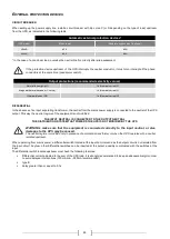
We recommend that the INPUT/OUTPUT and the BATTERY cables pass under the UPS.
As for the dimensioning of the cross section of the input and output cables, please refer to the following table:
Cross section of cables (mm
2
)
*
INPUT
mains /
separate bypass (optional)
OUTPUT
EXTERNAL BATTERY ** (optional)
kVA
PE
L1/L2/L3
N
PE
L1/L2/L3
N
PE
+/-
N
30
16
16
16
16
16
16
16
16
16
40
16
25
25
16
25
25
16
25
25
*
The cross sections shown in this table refer to a maximum length of 10 metres
** The maximum length of the cables for connection to the optional Battery Box is 3 metres
Note:
the maximum cross section of the cables that can be inserted in the terminal board is:
25 mm
2
for trailing cables
35 mm
2
per rigid cables
C
ONNECTIONS
As for UPSs with separate bypass, please see the subsequent paragraph.
The very first connection to be carried out is that of the protection conductor (earth cable), which must be
connected to the terminal marked PE. The UPS must not operate without being connected to an earthing
system
THE INPUT NEUTRAL MUST ALWAYS BE CONNECTED
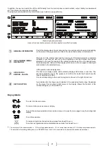
Connect the input and output cables to the terminal board as shown in the figure below:
Note 1
: The protection conductor (earth cable) connection must be carried out through eyelet terminal stud M6
Note 2:
Connections to the BATTERY module are required only when the Battery Box is present
(see paragraph "
Connecting the UPS to the Battery Box (optional)
")
Содержание SATURN
Страница 2: ......
Страница 40: ...40 MENU DISPLAY ...
Страница 60: ...60 ...
Страница 98: ...98 MENU DISPLAY ...
Страница 118: ...118 ...
Страница 156: ...156 DISPLAY MENÜ ...
Страница 176: ...176 ...
Страница 214: ...214 MENU AFFICHEUR ...
Страница 234: ...234 ...
Страница 272: ...272 MENÚ PANTALLA ...
Страница 292: ......
Страница 293: ......
Страница 294: ...0MNSATURNK30NP5LUC ...


