background image


- 18 - 

PMDF 1000


s

eleCting


the


tr ansmission


ProtoCol


s

et ting


the


Port


number


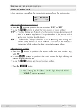
In this menu you can define the transmission protocol and the port number. 


Bx 4
UDP

MODE/PORT

  1234


Selecting the transmission protocol


•  Press the 

 button to position the cursor under ”

UDP

” or “

RTP

”.


•  Using the 

 buttons to select the transmission protocol wished:


UDP

” –  The User Datagram Protocol is for the connectionless transmission of 

data to a certain application. The port number of the service is also 
sent which the data should obtain.


RTP

” –  The Real-time Transport Protocol is for continuously transmitting mul-

timedia  data  streams  in  an  IP  network.  Unlike  UDP,  the  header  is 

transmitted which makes the data transmission more robust.


Setting the port number


•  Press  the 

  button  to  position  the  cursor  under  the  port  number  e.g. 

  1234

”.


•  Use  the 

  buttons  to  position  the  cursor  under  the  digit  of  the  port 

number displayed to be set.


•  Using the 

 buttons set the port number wished.


•  Press the 

 button.

 —>  The  “Setting  the  IP  address  of  the  input  transport  stream”  – 

IP-INPUT

” menu is activated.

Содержание HMPT 1000 FM

Страница 1: ...ASS KLASSE PMDF 1000 Head End Modulator FM IP to 12xFM GSS Grundig SAT Systems GmbH Beuthener Strasse 43 D 90471 Nuremberg Phone 49 0 911 703 8877 Fax 49 0 911 703 9210 E mail info gss de Internet http www gss de ...

Страница 2: ...ng the cassette 14 Selecting the cassette 14 Setting the Ethernet parameters 15 Setting the IP address of the cassette 15 Setting the address range 16 Setting the address of the gateway 16 Setting the UDP port 17 Setting the input parameters 17 Selecting the transmission protocol 18 Setting the port number 18 Setting the IP address of the input transport stream 19 Delete programme locations 20 Pro...

Страница 3: ...s No liability is accepted for any damage caused by faulty connections or inappropriate handling Observe the relevant standards regulations and guidelines on the installa tion and operation of antenna systems The standards IEC EN DINEN50083 resp IEC EN DINEN60728 must be observed For further information please read the assembly instructions for the head end station used Test the software versions ...

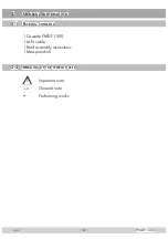
Страница 4: ...DF 1000 2 General information 2 1 Packing contents 1 Cassette PMDF 1000 1 LAN cable 1 Brief assembly instructions 1 Messprotokoll 2 2 Meaning of the symbols used Important note General note Performing works ...

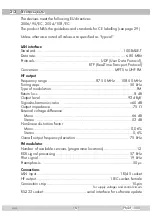
Страница 5: ... 50 MHz 108 00 MHz Tuning steps 50 kHz Type of modulation FM Return loss 8 dB Output level 93 dBμV Signal to harmonics ratio 60 dB Output impedance 75 Ω External voltage difference Mono 66 dB Stereo 53 dB Non linear distortion factor Mono 0 06 Stereo 0 6 Overall output frequency deviation 75 kHz FM modulator Number of available services programme locations 12 RDS signal processing 57 kHz Pilot sig...

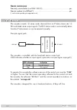
Страница 6: ...ut LAN input IP data stream Combiner 12 fold modulator TPS The cassette is controlled with the head end station control unit A LED indicates whether an input signal is present or not see figure on page 5 LED indicator Indication Green Signal present Red No signal To operate this cassette the software version of the control unit must be V 44 or higher You can find the current operating software for...

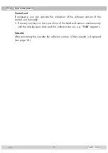
Страница 7: ...e software version of the control unit manually Press any two keys on the control unit of the head end station simultaneously until the display goes dark and the software version e g V 44 appears Cassette After activating the cassette the software version of the cassette is displayed see page 14 ...

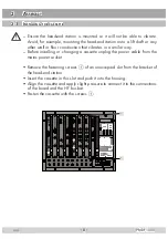
Страница 8: ...n that vibrates in a similar way Before installing or changing a cassette unplug the power cable from the mains power socket Remove the fastening screws 1 of an unoccupied slot from the bracket of the head end station Insert the cassette in this slot and push it into the housing Align the cassette and apply slight pressure to connect it to the connections of the board and the HF bus bar Fasten the...

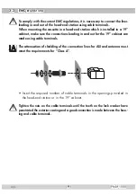
Страница 9: ...eading in and out for the 19 cabinet are made using cable terminals CLASS KLASSE The attenuation of shielding of the connection lines for ASI and antenna must meet the requirements for Class A Insert the required number of cable terminals in the openings provided in the head end station or in the 19 cabinet Tighten the nuts on the cable terminals until the teeth on the lock washer have penetrated ...

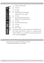
Страница 10: ...LED network connection 8 not used 9 Status LED of the LAN input 0 not used not used MAC address The operating software of the cassette can be updated via the 9 pin D SUB socket RS 232 using a PC or notebook and the software BE Flash You can find the current operating software on the website www gss de 3 4 Connecting the cassette Plug the LAN input cable into the LAN input socket Connect the head e...

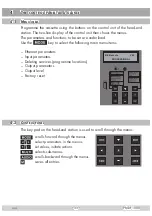
Страница 11: ...lined Use the key to select the following main menu items Ethernet parameters Input parameters Deleting services programme locations Output parameters Output level Factory reset 4 2 Control panel The key pad on the head end station is used to scroll through the menus scrolls forward through the menus select parameters in the menus set values initiate actions selects sub menus scrolls backward thro...

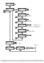
Страница 12: ...169 IP ADDR Bx 4 60000 UDP PORT 0 65535 Bx 4 UDP MODE PORT 1234 Bx 4 227 40 IP INPUT 50 60 UDP RTP 0 65535 Bx 4 LAN INPUT OK Bedienhinweise blättert Menüs vorwärts blättert Menüs rückwärts wählen die Eingabeposition wählt Untermenü stellen Werte ein speichert alle Eingaben 1 zeigt die Eingabeposition Operating Hints scrolls forward through the menu scrolls backward through the menu select the ente...

Страница 13: ...VOLUME C FM 01 AUDIO AUTO FM 01 Bayern 1 RDS NAME auto 0 10 dB Bx 4 FM SERVICES CLEAR ALL AUTO MONO STEREO M B A Bx 4 Defaults FACTORY Bx 4 STORE FACTORY M auf Werkseinstellung zurücksetzen und speichern reset to factory defaults and store FM 01 12 FM 12 01 FM 01 12 FM 12 01 FM 01 12 FM 12 01 FM 01 12 FM 12 01 FM 01 12 FM 12 01 FM 01 12 FM 12 01 FM 01 12 FM 12 01 zu klein too small OK C Begrenzung...

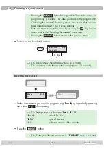
Страница 14: ... to the previous menus Switch on the head end station Ein On BE Remote please wait V 44 t 10 s The display shows the software version e g V 44 The processor reads the cassettes data approx 10 seconds Selecting the cassette Box 4 V 1 IP FM Bx 1A C5 12 S3 24 TWIN SAT C07 Böx 4 C5 12 S3 24 TWIN SAT C07 Box 5 Box Select the cassette you want to program e g Box 4 by repeatedly pressing the button if ne...

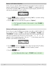
Страница 15: ... IP address of the cassette menu IP ADDR is activated Setting the IP address of the cassette If you choose to enter the Ethernet parameters manually set the IP address of the cassette in this menu If DHCP is selected the IP ADDR IP MASK and IP GATEWAY sub menus display the parameters that were assigned automati cally by a connected server If a server is not connected 0 0 0 0 appears in the corresp...

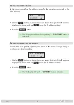
Страница 16: ... IP address wished Press the button The Setting the address of the gateway IP GATEWAY menu is activated Setting the address of the gateway The address of a gateway server can be set in this menu If no gateway is used you can skip this setting Bx 4 192 168 1 1 IP GATEWAY Use the buttons to place the cursor under the digit of the IP address displayed to be set and use to set the IP address wished Pr...

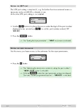
Страница 17: ...mber displayed to be set and use to set the port number wished 0 65535 Press the button The Setting the input parameters INPUT main menu is activated Setting the input parameters Via this menu you have access to the submenus for the input parameters Bx 4 LAN INPUT OK Press the button The Selecting the transmission protocol setting the port number MODE PORT menu is activated With the button the inp...

Страница 18: ...n application The port number of the service is also sent which the data should obtain RTP The Real time Transport Protocol is for continuously transmitting mul timedia data streams in an IP network Unlike UDP the header is transmitted which makes the data transmission more robust Setting the port number Press the button to position the cursor under the port number e g 1234 Use the buttons to posi...

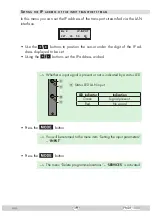
Страница 19: ...the digit of the IP ad dress displayed to be set Using the buttons set the IP address wished Whether a input signal is present or not is indicated by a status LED 1 2 3 4 5 7 6 8 9 0 9 Status LED LAN input LED indicator Indication Green Signal present Red No signal Press the button You will be returned to the menu item Setting the input parameters INPUT Press the button The menu Delete programme l...

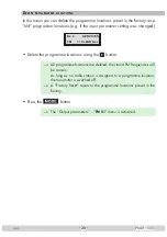
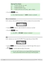
Страница 20: ...nged Bx 4 FM SERVICES CLEAR ALL Delete the programme locations using the button All programme locations are deleted the stored FM frequencies will be remain As long as no radio station is assigned to a programme location the transmitter is switched off A Factory Reset resets to the programme locations preset in the factory Press the button The Output parameters FM 01 menu is activated ...

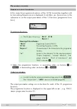
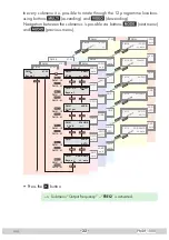
Страница 21: ...tting frequency in MHz Bayern 1 Channel name of the channel set to this programme location Access to the submenus for the output parameters Output frequency channel selection Lan guage selection Kind of transmission and RDS via button Select the programme locations in ascending order via buttons or in descending order via buttons or Output parameters In order to skip the output parameter settings ...

Страница 22: ...50 FM 04 FREQ auto FM 04 RA 001 091 FM 04 AUDIO FM 04 VOLUME FM 04 AUDIO AUTO FM 04 RDS NAME auto FM 03 87 50 FM 03 FREQ auto FM 03 RA 001 091 FM 03 AUDIO FM 03 VOLUME FM 03 AUDIO AUTO FM 03 RDS NAME auto FM 02 87 50 FM 02 FREQ auto FM 02 RA 001 091 FM 02 AUDIO FM 02 VOLUME FM 02 AUDIO AUTO FM 02 RDS NAME auto FM 01 Bayern 1 87 50 FM 01 87 50 FREQ auto FM 01 RA Bayern 1 001 091 FM 01 01 01 ger AUD...

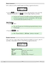
Страница 23: ...atically in 300 kHz steps from the displayed programme location on auto function Press the button The output frequencies of the following programme locations are set automatically Press the button The Channel selection 001 xxx submenu is activated Channel selection In this menu you assign which of the channels available via tuner A tuner B and ASI is transmitted via the corresponding programme loc...

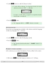
Страница 24: ...lection AUDIO submenu is activated Language selection If more than one languages are available in this submenu select the language wished e g language 1 of 1 German FM 01 01 01 ger AUDIO Use the buttons to select the language wished Press the button The Frequency deviation adjustment VOLUME submenu is ac tivated Frequency deviation adjustment In this submenu you can adjust the deviation This has e...

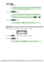
Страница 25: ...n can be set stereo mono automatic FM 01 AUDIO AUTO Use the buttons to select the kind of transmission wished Press the button The RDS RDS NAME submenu is activated RDS In this submenu you can enter the RDS Programme Service Name PS FM 01 Bayern 1 RDS NAME auto Use the buttons to position the cursor under the digit of the name to be set Press to set the respective digit of the name Via the auto fu...

Страница 26: ...u will be returned to the Programme location FM 01 main menu If necessary adjust another programme locations Press the button The Output level LEVEL main menu is activated Output level In this menu the output level can be adjusted 0 10 dB Bx 4 LEVEL 0 dB With the buttons adjust the output level wished Press the button The Factory reset FACTORY main menu is activated ...

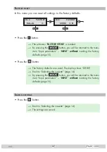
Страница 27: ...eturned to the menu item Input parameters INPUT without invoking the factory defaults page 15 Press the button The factory defaults are saved The display shows STORE Back to Selecting the cassette page 14 By pressing the button you will be returned to the menu item Input parameters INPUT without invoking the factory defaults page 15 Saving settings Press the button Back to Selecting the cassette p...

Страница 28: ...ttes it is necessary to tighten all cable connections cable terminals and cover screws in order to maintain compliance with current EMC regulations securely Securely tighten the cable bolted connections using an appropriate open ended spanner Mount the front cover see assembly instructions of the head end station ...

Страница 29: ... 29 PMDF 1000 Declaration of CE conformity ...

Страница 30: ...Alterations reserved Technical data E O E by GSS GmbH V1 14122010 Service Phone 49 0 911 703 2221 Fax 49 0 911 703 2326 Email service gss de ...

Отзывы: