37
Fan and Heater
ALWAYS DISCONNECT
AND LOCK OUT POWER
BEFORE WORKING ON OR
AROUND HEATER
OPERATING PROCEDURE
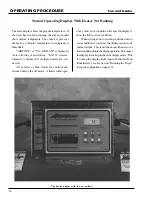
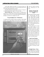
The control panel display showing initial start up.
All safety and high limit switches are checked upon power
up. If a safety or limit is open, the control displays it.
The control cannot operate with a safety switch error,
and the fan cannot turn on with an error condition. There
Standard electrical safety practices and codes should
be used when working with a heater. Refer to the
National Electric Code Standard Handbook by
the National Fire Protection Association.
A quali-
fied electrician should make all wiring instal-
lations.
Power Up
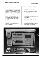
the controller locks up with the main display
alternating between a "FAN" and "ON" message.
This may be bypassed by depressing and holding
the "FAN BYPASS" switch (lower right switch).
Normal operating procedure should be to power up
the controller with the fan off.
If multiple heaters are tied together, and the
master detects that the slave fan is on (the air
switch stuck?), the master will lock up displaying
"SLA ERROR". This condition may be bypassed
with the "FAN BYPASS" switch.
is no way to bypass an error condition. It
must be fixed.
(See errors on page 21)
The air switch is also checked on power up.
The air switch must indicate no airflow. This is
necessary to check the function of the air switch.
However, if the operator forgets and turns the
fan on before the controller has been powered
up,
Содержание PNEG-377
Страница 1: ...Fan And Heater PNEG 377 Service Manual 2 0 0 0 EDITION...
Страница 2: ......
Страница 6: ...6 Fan and Heater...
Страница 7: ...7 Fan and Heater 2000 VANE AXIAL FANS...
Страница 9: ...9 Fan and Heater TEST STATION...
Страница 14: ...14 Fan And Heater FAN WIRING AND SCHEMATIC Wiring 240 Volt 1 Phase 15 HP Schematic...
Страница 17: ...17 Fan And Heater 2000 CENTRIFUGAL FAN SERVICE GUIDE...
Страница 21: ...21 Fan and Heater FAN SCHEMATIC AND WIRING 240 Volt 1 Phase 15 HP Marathon Schematic Wiring Diagram...
Страница 24: ...24 Fan and Heater 2000 Gas Heater Service Guide...
Страница 49: ...49 Fan and Heater WIRING DIAGRAM...
Страница 56: ...56 Fan and Heater WIRING SCHEMATIC...
Страница 57: ...57 Fan and Heater STANDARD HEATER WIRING...
Страница 58: ...58 Fan and Heater STANDARD HEATER SCHEMATIC...
Страница 61: ...61 Fan and Heater NOTES Notes...
Страница 62: ...62 Fan And Heater 1996 1994 Gas Heaters...
Страница 63: ...63 Fan And Heater DELUXE HEATER WIRING...
Страница 64: ...64 Fan And Heater DELUXE HEATER SCHEMATIC...
Страница 65: ...65 Fan And Heater DELUXE HEATER SCHEMATIC 1993 1995 Heaters...
Страница 70: ...70 Fan and Heater 1991 1993 GAS HEATERS...
Страница 72: ...72 Fan And Heater WIRING SCHEMATIC 1991 1992 Heaters...
Страница 73: ...73 Fan and Heater 1990 GAS HEATERS...
Страница 76: ...76 Fan and Heater PRE 1990 GAS HEATERS...
Страница 77: ...77 Fan and Heater HEATER WIRING DIAGRAM...
Страница 78: ...78 Fan and Heater HEATER SCHEMATIC Vane Axial LP Heater...
Страница 79: ...79 Fan and Heater HEATER SCHEMATIC Vane Axial Vapor Heater...
Страница 80: ...80 Fan and Heater HEATER SCHEMATIC Downwind LP Heater...
Страница 81: ...81 Fan and Heater HEATER SCHEMATIC Downwind Vapor Heater...
Страница 82: ...82 Fan and Heater HEATER SCHEMATIC Lo Fire Downwind Heater...
Страница 83: ...83 Fan and Heater MISCELLANEOUS INFORMATION...
Страница 93: ...93 Fan and Heater FENWAL SERIES 05 14 Figure 2 Figure 3...
Страница 97: ...97 Fan And Heater...
Страница 98: ...1004 E Illinois St Assumption IL 62510 Phone 217 226 4421 Fax 217 226 4498 February 2000...


