


68
Fan And Heater
Light Identification
Light 1
Signifies the on/off switch is on
and the heater hi-limit is good.
Light 2
Signifies the fuse is good.
Light 3
Signifies the 10 second time delay
relay and/or the DPDT relay is
energized.
Light 4
Signifies the vapor hi-limit is
closed, or set, not tripped out.
Light 5
Signifies the humidistat-thermostat
is calling for heat.
Light 6
Signifies the DPDT relay, vapor
solenoid, liquid solenoid, ignition
transformer and indication light are
receiving power.
Light 7
Signifies the cycle thermostat is
closed and the cycle solenoid is
receiving power.
Light A
Signifies the flame probe is closed.
Light B
Signifies the DPDT relay is
energized and the time delay reset
is receiving power.
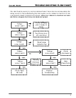
Troubleshooting Chart
Light #
Description
0
If no light is on, first check the on/
off switch to be sure it is in the on
position. If the unit still does not
operate, check the heater hi-limit.
1
If light #1 is the only one lit,
check the fuse on the SMART
BOARD. If faulty, replace.
1 and 2
If only lights 1 and 2 are lit,
check your connections to the
flame detection module. (blue/
black and white/brown wires). If
connection is good replace flame
detection module.
1,2 and A
If onlylights 1,2 and A are lit,
check the 10 second purge relay
and/or the DPDT relay. Replace
either part if faulty and restart
unit.
1,2,3 and A
If only lights 1,2,3 and A re lit
the vapor hi-limit has shut down
the unit. If the unit has been
operating and just shut down,
allow time for the vapor high
limit to cool down (2 or 3
minutes). The vapor hi-limit
will automatically reset itself.
Then, readjust the vaporizer to a
cooler position and the unit will
restart itself. If it will not restart
check and/or replace vapor hi-
limit.
1,2,3,4 and A
If only lights 1,2,3,4 and A are
lit, the humidistat thermostat or
other heater control device has
shut down the unit. Allos time
for thermostat to cool and if unit
does norestart check and/or
replace control device.
1-5 and A
If only lights 1-5 and A are lit
the time delay reset has shut
down the unit. Reset the delay
and restart the unit. If the delay
connot be reset then replace. (If
reset keeps kicking out flame
sensor may be bad or need to be
adjusted into the flame).
1-6, A and B
Check to see that spark plug is
giving good blue sparkplug is
giving good blue spark. If spark
plug is not sparking check
transformer, spark plug and
spark plug wire. If unit does
have good spark check to be sure
that gas supply is on.
SMART BOARD
Содержание PNEG-377
Страница 1: ...Fan And Heater PNEG 377 Service Manual 2 0 0 0 EDITION...
Страница 2: ......
Страница 6: ...6 Fan and Heater...
Страница 7: ...7 Fan and Heater 2000 VANE AXIAL FANS...
Страница 9: ...9 Fan and Heater TEST STATION...
Страница 14: ...14 Fan And Heater FAN WIRING AND SCHEMATIC Wiring 240 Volt 1 Phase 15 HP Schematic...
Страница 17: ...17 Fan And Heater 2000 CENTRIFUGAL FAN SERVICE GUIDE...
Страница 21: ...21 Fan and Heater FAN SCHEMATIC AND WIRING 240 Volt 1 Phase 15 HP Marathon Schematic Wiring Diagram...
Страница 24: ...24 Fan and Heater 2000 Gas Heater Service Guide...
Страница 49: ...49 Fan and Heater WIRING DIAGRAM...
Страница 56: ...56 Fan and Heater WIRING SCHEMATIC...
Страница 57: ...57 Fan and Heater STANDARD HEATER WIRING...
Страница 58: ...58 Fan and Heater STANDARD HEATER SCHEMATIC...
Страница 61: ...61 Fan and Heater NOTES Notes...
Страница 62: ...62 Fan And Heater 1996 1994 Gas Heaters...
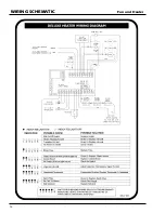
Страница 63: ...63 Fan And Heater DELUXE HEATER WIRING...
Страница 64: ...64 Fan And Heater DELUXE HEATER SCHEMATIC...
Страница 65: ...65 Fan And Heater DELUXE HEATER SCHEMATIC 1993 1995 Heaters...
Страница 70: ...70 Fan and Heater 1991 1993 GAS HEATERS...
Страница 72: ...72 Fan And Heater WIRING SCHEMATIC 1991 1992 Heaters...
Страница 73: ...73 Fan and Heater 1990 GAS HEATERS...
Страница 76: ...76 Fan and Heater PRE 1990 GAS HEATERS...
Страница 77: ...77 Fan and Heater HEATER WIRING DIAGRAM...
Страница 78: ...78 Fan and Heater HEATER SCHEMATIC Vane Axial LP Heater...
Страница 79: ...79 Fan and Heater HEATER SCHEMATIC Vane Axial Vapor Heater...
Страница 80: ...80 Fan and Heater HEATER SCHEMATIC Downwind LP Heater...
Страница 81: ...81 Fan and Heater HEATER SCHEMATIC Downwind Vapor Heater...
Страница 82: ...82 Fan and Heater HEATER SCHEMATIC Lo Fire Downwind Heater...
Страница 83: ...83 Fan and Heater MISCELLANEOUS INFORMATION...
Страница 93: ...93 Fan and Heater FENWAL SERIES 05 14 Figure 2 Figure 3...
Страница 97: ...97 Fan And Heater...
Страница 98: ...1004 E Illinois St Assumption IL 62510 Phone 217 226 4421 Fax 217 226 4498 February 2000...


