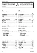
Allgemeiner Teil / General Section
M 100-CD MKII
1 - 6
GRUNDIG Service
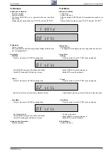
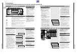
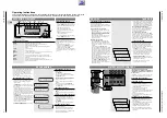
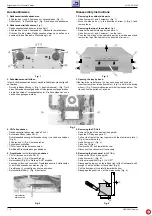
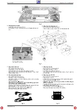
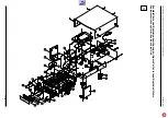
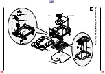
Fig. 3
Fig. 1
Fig. 2
A
Ausbauhinweise
1. Gehäuseseitenteile abnehmen
- 2 Schrauben
A
und 2 Schrauben
B
herausdrehen (Fig. 1).
- Seitenteile
C
in Pfeilrichtung
D
(Fig. 2) schieben und abnehmen.
2. Gehäuseoberteil abnehmen, Fig. 2
- Gehäuseseitenteil abnehmen (siehe Pkt.1).
- 4 Schrauben
E
und 2 Schrauben
F
(Rückseite) herausdrehen.
- Drücken Sie die beiden Gehäuseseiten etwas nach außen und
nehmen Sie das Oberteil in Pfeilrichtung
G
ab.
3. Schublade manuell öffnen
Ist der Schubladenantrieb defekt, kann die Schublade manuell geöff-
net werden:
- Durch die Bodenöffnung
H
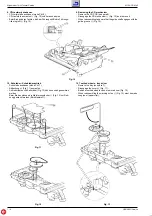
(Fig. 1) das Antriebsrad
I
(Fig. 7) mit
einen Schraubendreher gegen den Uhrzeigersinn solange drehen,
bis die Schublade 1cm ausgefahren ist. Die Schublade kann nun
nach außen gezogen werden.
4. CD-Teil ausbauen
- Gehäuseoberteil abnehmen (siehe Pkt. 2).
- Schublade öffnen (siehe Pkt. 3).
- Schubladenabdeckung mit Aluabdeckung
J
nach oben abziehen
(Fig. 2).
- 2 Schrauben
K
(Fig. 3) herausdrehen.
- Schubladen schließen.
- CD-Teil nach hinten herausnehmen.
- Bei Bedarf Steckverbindungen abziehen.
5. Frontblende (mit Leiterplatten) ausbauen
- CD-Teil ausbauen (siehe Pkt. 4).
- 2 Schrauben
L
(Fig. 6) herausdrehen.
- Netzschalter (Fig. 4) in Stellung "AUS" schalten.
- Laschen
M
links und rechts der Frontblende sowie 2 Haltezapfen
N
am Gehäuseboden ausrasten (Fig. 5).
- Frontblende
O
vorsichtig nach vorne abziehen.
- Netzschalterstößel
P
(Fig. 4) ausrasten.
Disassembly Instructions
1. Removing the cabinet side parts
- Undo 2 screws
A
and 2 screws
B
(Fig. 1).
- Move the side parts
C
in the direction of arrow
D
(Fig. 2) and
remove them.
2. Removing the top of the cabinet, Fig. 2
- Remove the cabinet side parts (see para 1).
- Undo 4 screws
E
and 2 screws
F
(on the rear).
- Push the two sides of the cabinet apart by a small amount and
remove the top of the cabinet in the direction of arrow
G
.
3. Opening the tray by hand
If the tray driver is defective, the tray can be opened by hand:
- Insert a screw driver into bottom hole
H
(Fig. 1) and turn the driving
wheel
I
(Fig. 7) counterclockwise until the tray is opened 1cm. The
tray can now be pulled out by hand.
4. Removing the CD Unit
- Remove the top of the cabinet (see para 2).
- Open the CD tray (see para 3).
- Pull out the front of the tray together with the aluminium plate
J
(Fig. 2) towards the top.
- Undo 2 screws
K
(Fig. 3).
- Close the CD tray.
- Remove the CD unit towards the rear.
- Disconnect the connectors if necessary.
5. Removing the front panel (with PCBs)
- Remove the CD unit (see para 4).
- Undo 2 screws
L
(Fig. 6).
- Set the mains switch (Fig. 4 ) to "OFF".
- Disengage the lugs
M
on the left and right of the front panel and 2
prongs
N
on the bottom of the cabinet (Fig. 5).
- Pull the front panel
O
carefully towards the front.
- Disengage the push-rod
P
of the mains switch (Fig. 4).
Fig. 4
Fig. 5
A
B
B
H
(
I
)
E
D
F
F
G
E
D
K
K
J
Netzschalter
Mains switch
P
N
M
O
C
C


