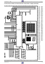
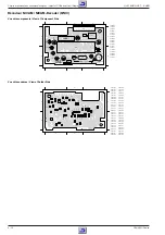
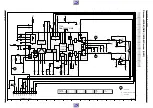

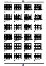


GRUNDIG Service
5 - 5
GV 27 EURO, GV 7… EURO
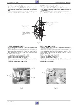
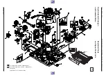
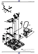
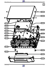
Platine mécanique / Drive Mechanism
Fig. 9
Fig. 8
Fig. 10
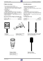
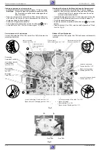
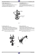
2.3 Headwheel
Note:
The extractor (part no. 75988-002.37) is necessary to remove
the headwheel.
Do not touch the headwheel with bare hands. Wear the nylon
gloves.
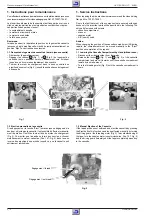
Removal:
– Insert the reference pin "C" (delivered with each service headwheel)
into the hole of the scanner motor and turn the headwheel until the
pin locks into the hole of the rotor (Fig. 7).
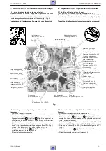
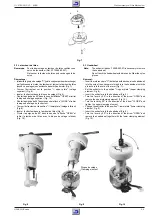
– Set the extractor to the position "
3
upper plate" (upper clamping
element, Fig. 8).
– Insert the extractor into the headwheel (Fig. 9).
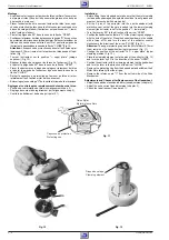
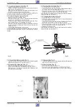
– Turn the lever by 90
°
in the direction of the arrow "OPEN" and
remove the upper clamping element (Fig. 10).
– Turn the lever by 90
°
in the direction of the arrow "CLOSE" and
tighten the upper clamping element.
– Change the extractor to the position "
0
lower plate" (lower clamping
element, Fig. 8).
– Insert the extractor into the headwheel (Fig. 9).
– Turn the lever by 90
°
in the direction of the arrow "OPEN" and
remove the headwheel together with the lower clamping element
(Fig. 10).
Fig. 7
A
B
Disque de calage
Clamping element
2.3 Le tambour de têtes
Remarque:
Pour le démontage du tambour de têtes veuillez vous
servir de l'extracteur (Réf. N
°
75988-002.37).
Ne toucher le tambour de têtes qu'avec des gants de
nylon.
Démontage:
– Introduire le goujon de calage "C" (joint à chaque tambour de rechange)
par l'orifice sous le moteur de tambour et tourner le tambour de têtes
jusqu'à ce que le goujon s'enclenche dans l'orifice du rotor (Fig. 7).
– Tourner l'extracteur sur la position "
3
upper plate" (calage
supérieur) (Fig. 8).
– Insérer l'extracteur dans le disque de calage (Fig. 9).
– Pivoter la poignée de 90
°
dans le sens de la flèche "OPEN" et retirer
le disque de calage supérieur (Fig. 10).
– Pivoter la poignée de 90
°
dans le sens de la flèche "CLOSE" et retirer
le disque de calage de l'extracteur.
– Tourner l'extracteur sur la position "
0
lower plate" (calage inférieur)
(Fig. 8).
– Insérer l'extracteur dans le tambour de têtes (Fig. 9).
– Pivoter la poignée de 90
°
dans le sens de la flèche "OPEN" et
retirer le tambour de têtes avec le disque de calage inférieur
(Fig. 10).


