background image

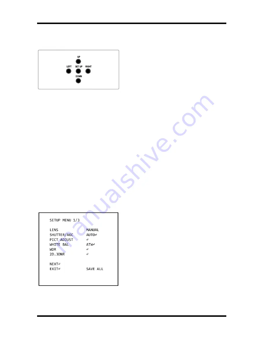
5. OSD Control Keys

5.1. OSD Control Keys on Rear Panel


- SET UP key (in the middle): Accesses the 
menu mode or confirms the setting.


- UP / DOWN: Chooses the desired menu.


- LEFT / RIGHT: Sets up the value of the 
selected menu and changes the settings.

5.2. Coax Controller (optional)

The Coax Controller 

GKB-A0040P

 (optional) can be used for adjusting the OSD menu 

settings of this camera.

6. OSD Menu

1. Press the SET UP key and hold it for a while to access the menu mode.
2. Select the desired feature by using the UP/DOWN keys. 
3. If there is a setting for this feature on the the right side of the screen, use the 
LEFT/RIGHT keys to switch between the settings and confirm your choice by pressing 
the SET UP key. If an ENTER arrow (

) is displayed, press SET UP to access the 

according submenu.
4. When the settings are completed, go to SAVE ALL and press the SET UP key to save 
the settings. If you have not done this and the power is turned off, the changes in the 
settings will not be kept.
5. In the sub-menus, please press with the SET UP key on RETURN to return to the 
previous menu.
6. Please press with the SET UP key on NEXT or BACK to switch between the SETUP 
MENU pages. 
7. To exit the menu, please press with the SET UP key on EXIT in the main menu.

LENS: Here you can configure the lens 
setting.

SHUTTER/AGC: This function is used to 
control the light exposure.

PICT ADJUST: You can set different picture 
related settings like mirroring, sharpness, 
contrast, hue and gain.

WHITE BAL: You can control the white 
balance under different lighting conditions 
here.

6

English

Содержание GCA-B1005B

Страница 1: ...GCA B1005B 77 1 11 10 2012 Owner s Manual EN ASP AG Cameras Domes GCA B1005B 1 3 CCD Colour B W Camera WDR 650L 230VAC GCA B1305B 1 3 CCD Colour B W Camera WDR 650L 12VDC 24VAC...

Страница 2: ......

Страница 3: ...Power Connection 5 5 OSD Control Keys 6 1 OSD Control Keys on Rear Panel 6 2 Coax Controller optional 6 6 OSD Menu 6 1 LENS 8 2 SHUTTER AGC 8 3 PICT ADJUST Picture Adjustment 10 4 WHITE BAL White Bala...

Страница 4: ...e single adapter Exceeding the capacity may cause abnormal heat generation or fire Do not place conductive objects e g screwdrivers coins or any metal items or containers filled with water on top of t...

Страница 5: ...r electric shock Install it in a place with good ventilation When installing the unit fasten it securely and firmly A falling unit may cause personal injury If you want to relocate the already install...

Страница 6: ...C CS Mount Adapter between the camera and the C Mount lens as shown in the illustration below 4 3 Back Focus Adjustment When to adjust the back focus Back Focus refers to the distance from the rear le...

Страница 7: ...back focus adjustment on the test chart Step 5 Set the zoom now to the most extreme telephoto position Step 6 Focus on the object with the focus screw of the lens not with the back focus adjustment I...

Страница 8: ...ressing the SET UP key If an ENTER arrow is displayed press SET UP to access the according submenu 4 When the settings are completed go to SAVE ALL and press the SET UP key to save the settings If you...

Страница 9: ...ilisation will set the anti shake compensation PRIVACY You can mask specific areas in the monitoring area here MOTION DET This function is used to detect moving objects in the monitoring area NEXT Cho...

Страница 10: ...is too high the iris might operate improperly MANUAL Select this item for the manual iris lens 6 2 SHUTTER AGC This function is used to control the light exposure You can either select AUTO for the au...

Страница 11: ...n AGC SLOW2 The auto exposure is controlled by using AGC for higher and lower low lux values and by using slow shutter mode for midlow low lux values Adjust the AGCMID level to determine when the slow...

Страница 12: ...t of the image the difference between light and dark areas on the screen SHARPNESS 000 015 This function is used to adjust the sharpness of the displayed image HUE 000 100 This function is used to adj...

Страница 13: ...temperature ENVIRONMENT INDOOR OUTDOOR Choose INDOOR when the camera is installed indoors this is mainly for sodium vapor lamps or indoor lighting conditions it means ATW is set to Low Colour Tempera...

Страница 14: ...a strong blue tone on the screen LEVEL DOWN Keep pressing with the SET UP key on PUSH ENTER to decrease the white balance level A decreased level produces a strong red tone on the screen PRESET When...

Страница 15: ...ou can set different levels here 6 7 HLC BLC When selecting the following submenu will appear HLC High Light Compensation OFF ON AUTO This function is used to surpress or mask a strong light source fo...

Страница 16: ...according ambient illumination brightness is reached BURST Set this option to ON to output a burst signal in B W mode DELAY CNT Sets the delay time for switching between COLOR and B W mode DAY NIGHT S...

Страница 17: ...nction improves the visibility of the entire picture by providing the optimum gradation compensation for the image in one field based on the luminance information If you choose CENTER for SMART IR in...

Страница 18: ...he other way round COLOR If set to COLOR the camera will be fixed to COLOR mode regardless of the ambient conditions 6 9 EZOOM When selecting the following submenu will appear When you enter this subm...

Страница 19: ...for each corner of the mask area Press SET UP again to leave this setting COLOR BLACK RED GREEN BLUE YELLOW CYAN MAGENTA WHITE Choose one of 8 colours for the mask areas TRANSP 0 00 0 5 0 75 1 0 Choo...

Страница 20: ...ting press the SET UP key and hold it for a while MONITOR AREA If you choose this item a submenu will appear where you can set the areas for motion detection monitoring AREA SEL 1 4 4 4 Select a monit...

Страница 21: ...y to be able to move the display position of the CAMERA ID Steps for programming the Camera ID 1 Turn on the CAMERA ID mode and enter the submenu 2 Using the four direction keys switch between the cha...

Страница 22: ...etection and compensation SUCCESS will show up on the monitor when less than 64 white pixels were detected then the pixels will turn from white to black ERROR shows up on the screen when more than 64...

Страница 23: ...hutter 1 50 1 100 000 sec auto BLC BLC HLC off AGC Off On x0 25 x0 5 x0 75 x1 Digital Noise Reduction DNR Low Midlow Mid Midhigh High Off 2D 3D Digital Image Stabilization DIS Off On Additional Featur...

Страница 24: ...Dimensions 22 English...

Страница 25: ...ed that the products meet the standards in the following relevant provisions EC EMC Directive 2004 108 EC Low Voltage Directive 2006 95 EC Applied harmonised standards and technical specifications EN...

Отзывы: