


English (GB)
23
• Set the current source to 5.6 mA (this corresponds to 10 %).
This and the following step cannot be done without a current
source.
• Check the dosing flow indicated by the measuring tube.
If this is not 10 %:
Reset the zero point. The floater may reach the end stop if the
dosing flow exceeds 0 %.
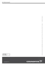
• Set the current sensor to 20 mA. Use programming buttons L
and SET to set the servomotor to 100 % dosing flow
(as indicated by the measuring tube). The toothed rack on the
regulating valve must not protrude by more than 31 mm.
Fig. 42
Rate valve with gear rack
• Set the upper limit switch (SL) to a value slightly above 100 %.
• Remount the cover of the servomotor.
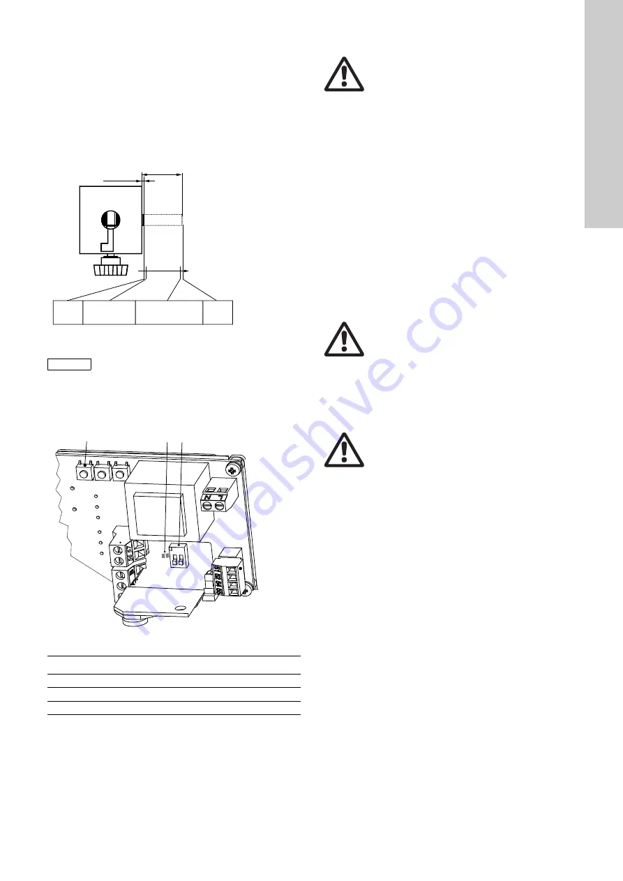
6.7.3 Manual operation of the servomotor
Fig. 43
Servomotor with analogue control
If necessary, the servomotor can also be operated manually.
• Remove the hood from the servomotor.
• Move the switch (item 5, 2) to 'Man'.
• Use programming buttons L or R (item 2) to move the
servomotor to the required position manually.
• Replace the hood on the servomotor.
Switch (item 5, 2) must be reset to 'Auto' for automatic mode.
6.8 Switching on
• Close the rate valve.
• Open the shut-off valve at the injection unit.
• Open the motive water valves.
• Switch on booster pump.
• Open valve of the gas container.
• Slowly open the rate valve until the desired gas flow is
displayed by the measuring tube.
6.9 Switching off
6.9.1 Emergency
• Put on safety equipment!
• Immediately close all container valves.
• Let the plant run until all parts are evacuated from the dosing
medium.
• Switch off the plant as described in the following.
6.9.2 Short-term stop (up to 6 hours)
• Close the rate valve.
• Switch off the booster pump.
• Close the motive water valves.
• Close the shut-off valve at the injection unit.
6.9.3 Long-term stop (while the plant is still running)
• Close all container valves.
• Let the plant run until the measuring tube shows no more gas
flow.
• Close the rate valve.
• Switch off booster pump.
• Close the motive water valves.
• Close the shut-off valve at the injection unit.
TM
04
08
27
09
08
Caution
In case of exceeding: The rate valve may get
damaged!
TM
04
09
60
40
09
Item
Description
2
Programming buttons
4
LEDs
5
DIP switch
31 mm
+0,5
1 mm
+0,5
min.
(ST1)
max.
(ST2)
Ymax
100% = 20 mA
^
Ymin
0% = 4 mA
^
2
5
4
1 2
L
R
SET
on
Warning
Danger!
Do not touch bare wires or clamp screws!
Warning
Immediately leave the room in case of gas break-out
and put on safety equipment!
Then start counter-measures!
Warning
Repairs of components of the system only by
authorized personnel!


