English (GB)
13
11.1.5 Removing the shaft seal
0.9 to 1.5 kW
1. See section
2. Remove the two screws (188a) in the middle securing the
shaft seal carrier (58), and fit them into the tapped extractor
holes in the shaft seal carrier.
3. Remove the shaft seal assembly by means of the two screws
(188a).
4. Pull out the shaft seal assembly (105).
5. Check the condition of the shaft where the secondary seal of
the shaft seal touches the shaft. The bush (103) fitted to the
shaft must be intact.
2.6 to 4.0 kW
1. See section
2. Remove the retaining ring (112a).
3. Remove the two screws (188a) in the middle securing the
shaft seal carrier (58), and fit them into the tapped extractor
holes in the shaft seal carrier.
4. Remove the shaft seal carrier (58) by means of the two
screws (188a).
5. Remove the retaining ring (112a).
6. Pull out the shaft seal assembly (105).
7. Check the condition of the shaft where the secondary seal of
the shaft seal touches the shaft. The bush (103) fitted to the
shaft must be intact.
11.1.6 Removing the bearings
1. See section
11.1.5 Removing the shaft seal
.
2. Remove the four screws (188a) from the oil chamber (155).
3. Remove the oil chamber (155) from the stator housing (55)
using screwdrivers (
). If the fitting is tight, remove the oil
chamber assembly by gently tapping the screwdrivers with a
plastic hammer (K).
4. Place the oil chamber assembly in a vice and check that the
rotor is not damaged.
5. Remove the O-rings (37a) from the oil chamber (155).
6. Pull out the bush (103) including the O-ring (102) from the
rotor/shaft (172).
7. Pull the oil chamber (155) out of the rotor/shaft (172) using a
puller.
8. Pull the lower bearing (153) out of the oil chamber (155).
9. Pull the upper bearing (154) off the rotor/shaft (172) using a
puller.
10. Remove the corrugated spring (158).
11.2 Assembling the product
Before assembling the product
• Clean and check all parts.
• Replace defective parts.
• Order the necessary service kits.
• Always replace gaskets and O-rings when the pump is
serviced.
During assembly
Lubricate and tighten screws and nuts according to section
.
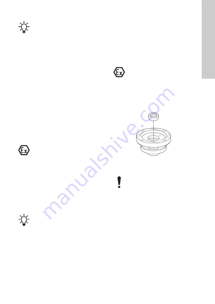
11.2.1 Fitting the bearings
Lower bearings
1. Clean the bearing in the oil chamber (155).
2. Heat the oil chamber (155) up to 100 °C.
3. Press the cold lower bearing (153) into the heated oil chamber
(155). See fig.
. Press and let the oil chamber cool. Use a
heat-resistance punch.
4. Allow the assembly to cool.
Fig. 12
Fitting the lower bearing in the heated oil chamber
5. Fix the rotor/shaft (172) in a vice with the shaft pointing
upwards.
The shaft seal is a complete unit for all SEG
AUTO
ADAPT
pumps.
Bearings of explosion-proof products must only be
replaced by Grundfos or a service workshop
authorised by Grundfos.
If you remove the rotor/shaft from the oil chamber, it
will break the lower bearing. Replace the broken
bearing.
Bearings of explosion-proof products must only be
replaced by Grundfos or a service workshop
authorised by Grundfos.
TM
0
4
6
984
1
810
To avoid damaging the rotor, do not overtighten the
vice. Use protection between vice and rotor.
Содержание seg autoadapt
Страница 1: ...SEG AUTOAdapt 0 9 4 0 kW DIN 50 Hz Service instructions GRUNDFOS INSTRUCTIONS ...
Страница 19: ...English GB 19 13 Drawings 13 1 Sectional drawing 0 9 to 1 5 kW TM06 6109 0716 6a Single phase pump only ...
Страница 20: ...English GB 20 13 2 Exploded view 0 9 to 1 5 kW TM06 5750 0316 ...
Страница 21: ...English GB 21 13 3 Sectional drawing 2 6 to 4 0 kW TM06 6111 0716 6a ...
Страница 22: ...English GB 22 13 4 Exploded view 2 6 to 4 0 kW Fig 21 SEG AUTOADAPT 2 6 4 kW TM06 5770 0316 ...


