background image

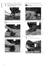
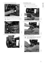
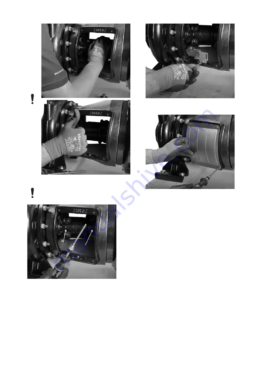
29. Make sure that the shaft runs freely.

30. Tighten the split coupling key set screws.

For the required torque, see Torques table.
Otherwise, hand-tighten the screws plus 15-20 de-
gress.

TM080421

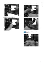
31. Re-install fork tool in motor stool holder.

TM080422

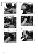
32. Tighten coupling guard screws.

• Tighten with 5 Nm or hand-tighten.

TM080423

Related information

6.1 Torque table

21

English (GB)

Содержание NBS

Страница 1: ...NBS NBSE Service instructions GRUNDFOS INSTRUCTIONS...

Страница 2: ......

Страница 3: ...NBS NBSE English GB Service instructions 4 3 Table of contents...

Страница 4: ...ions DANGER Indicates a hazardous situation which if not avoided will result in death or serious personal injury WARNING Indicates a hazardous situation which if not avoided could result in death or s...

Страница 5: ...production serial number 3 Flow 4 Head 5 Production code 6 Pressure and temperature 7 Pump speed 8 Impeller diameter 9 PEI CL Pump Energy Index constant load PEI VL Pump Energy Index variable load 10...

Страница 6: ...ylindrical trim for example 11 02 blank Closed impeller conical trim If two dimensions are shown the impeller has a conical trim for example 1094 1063 S Semi open impeller V Super vortex impeller 6 Hy...

Страница 7: ...50 05 316 No wear ring 304 SG 70 50 05 316 No wear ring 316 SH 70 50 05 316 No wear ring SAF 2205 T2 A48 Class 35 CD4MCuN A890 No wear ring SAF 2205 TA 70 50 05 CD4MCuN A890 No wear ring SAF 2205 X Sp...

Страница 8: ...A Carbon metal impregnated with antimony which is not approved for potable water B Carbon resin impregnated Q Silicon carbide Q Material of stationary seal A Carbon metal impregnated with antimony whi...

Страница 9: ...stead of the 200 hp 150 kW The pump is in scope of the DOE regulation and requires a PEI value and a motor code 2 2 3 Codes for phase and voltage or other information Pos 16 in NBSE NBS type key examp...

Страница 10: ...gon key Plastic hammer Pry bar 1 2 3 4 5 6 cm Tension Tester Torque wrench Punch for shaft seal Gauge for inner diameter meas urement of wear ring Soft jaws Pinch bar Sliding gauge Ratchet spanner wit...

Страница 11: ...vicing the product Check also the following service videos in association with this task How to dismantle and assemble Grundfos NBS single stage pump How to replace low pressure shaft seal on Grund fo...

Страница 12: ...ver is stuck to the pump housing cover use two seal cover screws as jacking bolts 10 Remove stationary part of the shaft seal from seal cover TM080367 11 Note O ring condition on shaft seal and on sea...

Страница 13: ...80373 16 Move motor enough to enable removal of motor stool TM080374 17 Loosen and remove motor stool from pump housing TM080366 18 Loosen pump cover from pump housing TM080376 19 Note 12 o clock posi...

Страница 14: ...e worn oval due to different directions of radial forces TM080471 2 Measure and note the bore in cover wear ring if fitted TM080381 3 Measure and note impeller interface to pump housing For maximum ga...

Страница 15: ...required torque see Torques table Apply thread lubricant where torque tightening is re quired Use locally approved thread lubricants for example NEVER SEEZ TM080386 TM080387 4 Check condition and clea...

Страница 16: ...d tighten nuts For the required torque see Torques table TM080391 TM080392 8 Assemble motor stool and motor and tighten nuts For the required torque see Torques table TM080393 9 Fit motor to support r...

Страница 17: ...0396 Make sure NOT to touch the seal face TM080397 12 Hand press the shaft seal into position until it rests against the impeller TM080398 13 Check condition and cleanliness of seal cover TM080399 14...

Страница 18: ...to touch the seal faces by hand TM080403 16 Use a soft tool to position the stationary seal part in seal cover TM080404 17 Apply thread lubricant where torque tightening is required Use locally approv...

Страница 19: ...TM080408 21 Assemble keys to motor and pump shaft TM080409 22 Use the fork tool to compress the shaft seal spring before assembling the split coupling TM080410 TM080411 Use locally approved thread lu...

Страница 20: ...080414 25 Keep the gap between the coupling pieces equal If you do not have an equal gap loosen the side with the smaller gap and tighten the side with the larger gap until both sides are equal TM0804...

Страница 21: ...or the required torque see Torques table Otherwise hand tighten the screws plus 15 20 de gress TM080421 31 Re install fork tool in motor stool holder TM080422 32 Tighten coupling guard screws Tighten...

Страница 22: ...move seal cover TM080364 2 If seal cover is stuck to the pump housing cover use two seal cover screws as jacking bolts 3 Remove stationary part of the shaft seal from seal cover TM080367 4 Note O ring...

Страница 23: ...ing in seal drive part TM080631 5 2 Assembling new seal 1 Clean pump shaft remove rust and debris Use steel brush or emery grinding paper TM080395 2 Check condition and cleanliness of new shaft seal d...

Страница 24: ...4 Drive part must rest against the impeller TM080635 5 Tighten set screws Hand tighten plus 15 20 degrees TM080636 6 Check condition and cleanliness of new shaft seal spring and seal face TM080637 Lub...

Страница 25: ...oved lubricants for example Rocol Sapphire Aqua SIL TM080400 TM080401 10 Spray soapy water on seal face of stationary shaft seal part Lubricate seal faces with soapy water shaft seal with seal face co...

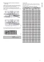
Страница 26: ...M14 65 7 M18 120 10 M24 300 35 M27 300 35 Pump cover nuts Nut Torque Nm M10 45 9 M12 80 16 M16 145 30 Motor stool pump housing nuts Nut Torque Nm M10 40 8 M1 70 15 M16 145 30 Motor stool motor bolts B...

Страница 27: ...inside Impeller outside Nominal diameter Max tolerance Min tolerance Nominal diameter Max tolerance Min tolerance 76 0 225 0 15 75 95 0 2 0 274 76 0 225 0 15 75 95 0 2 0 274 76 0 225 0 15 75 95 0 2 0...

Страница 28: ...00 0 34 0 455 144 6 0 1 0 144 0 28 0 38 224 65 0 115 0 224 0 38 0 495 174 6 0 1 0 174 0 31 0 41 224 65 0 115 0 224 0 38 0 495 210 65 0 115 0 210 0 38 0 495 Related information 4 2 Checking gap between...

Страница 29: ...ccording to the flow and head that the pump is selected for 2 Check the system for debris 3 Clean the system if necessary e The inlet pressure is too low Increase the liquid level on the inlet side Op...

Страница 30: ...operation causes noise Find the different remedies in Frequency converter opera tion section See section Frequency converter operation 4 The pump connections or mechanical shaft seal is leak ing a The...

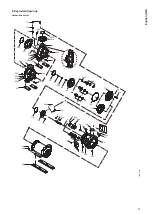
Страница 31: ...201 203 203b 66 20e 20e 20e 20e 20e 26 17a 17c 105 20e 20e 6 20e 26 90g 20e 105 105c 77a 77b 77f 1a 51 11 7 76 76a 7a 9 651a 11a 651 20g 20e 20e 90b 8 90a 28 89a 89b 36b 77 77 36 72a 105 26a 20e 90f...

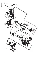
Страница 32: ...01b 66 20e 20 20e 20e 20e 17c 105 105 105c 77a 77b 77f 1a 51 11 7 76 76a 7a 9 651a 11a 651 20e 20e 90b 8 90a 28 89a 89b 36b 77 36 72a 105 26a 6 20e 20e 20e 20e 20e 24 26 90f 26 90f 90g 90h 90g 90h 90i...

Страница 33: ...90b 90a 77a 77b 77f 1a 51 11 7 76 76a 7a 9 651a 11a 651 20e 20e 8 28 36b 89a 89b 77 77 36 72a 105 509 6 20e 20 26 90f 26a 6 201b 201 203 203b 20e 26 90f 501 510 508 506 505 90g 90h 511 90i 90g 90h 20b...

Страница 34: ...OS Pumps Korea Ltd 6th Floor Aju Building 679 5 Yeoksam dong Kangnam ku 135 916 Seoul Korea Tel 82 2 5317 600 Fax 82 2 5633 725 Latvia SIA GRUNDFOS Pumps Latvia Deglava biznesa centrs Augusta Deglava...

Страница 35: ...demarks displayed in this material including but not limited to Grundfos the Grundfos logo and be think innovate are registered trademarks owned by The Grundfos Group All rights reserved 2021 Grundfos...

Отзывы: