English (GB)
19
8.3 Maintenance schedule
Inspect pumps running normal operation every 3000
operating hours or at least once a year. If the dry-
solid content of the pumped liquid is very high or
sandy, check the pump at shorter intervals.
Check the following points:
•
Power consumption
See section
.
•
Oil level and oil condition
When the pump is new or after replacement of
the shaft seal, check the oil level after one week
of operation.
Use Shell Ondina X420 oil or similar type. See
section
.
•
Sensors
For cleaning of sensors, see section
.
•
Cable entry
•
Pump parts
Check the impeller, the pump housing, etc. for
possible wear. Replace defective parts. See
section
.
•
Ball bearings
Check the shaft for noisy or heavy operation by
turning the shaft by hand. Replace defective ball
bearings.
A general overhaul of the pump is usually
required in case of defective ball bearings or poor
motor function. This work must be carried out by
Grundfos or a service workshop authorised by
Grundfos.
8.4 Oil check and oil change
Every 3000 operating hours or at least once a year,
change the oil in the oil chamber as described below.
If the shaft seal has been changed, the oil must be
changed as well.
The table below states the quantity of oil in the oil
chamber:
Draining of oil
1. Loosen and remove both oil screws to allow all
the oil to drain from the chamber.
2. Check the oil for water and impurities. If the shaft
seal has been removed, the oil will give a good
indication of the condition of the shaft seal.
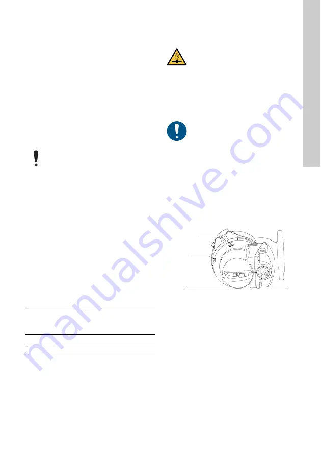
Oil filling, pump lying down
See fig.
1. Place the pump in such a position that it is lying
on the stator housing and the outlet flange and
that the oil screws are pointing upwards.
2. Fill oil into the oil chamber through the upper hole
until it starts running out of the lower hole. The oil
level is now correct.
3. Fit both oil screws using the gaskets included in
the O-ring service kit. See section
Fig. 14
Oil filling holes
Oil filling, pump in upright position
1. Place the pump on a plane, horizontal surface.
2. Fill oil into the oil chamber through one of the
holes until it starts running out of the other hole.
3. Fit both oil screws using the gaskets included in
the O-ring service kit. See section
Make sure that the cable entry is
watertight and that the cable is not sharply
bent and/or pinched.
Pump type
Quantity of oil
in the oil
chamber [l]
DP and EF pumps up to 1.5 kW
0.17
DP pumps of 2.6 kW
0.42
CAUTION
Pressurised system
Minor or moderate personal injury
- As pressure may have built up in the oil
chamber, do not remove the screws
until the pressure has been fully
relieved.
Dispose of used oil in accordance with
local regulations.
TM0
6
5
87
4 0
3
1
6
Oil level
Oil filling
Содержание DP AUTOADAPT Series
Страница 28: ...Appendix 28 Fig 4 Exploded view of DP 10 50 pump TM06 5879 0316...
Страница 29: ...Appendix 29 Fig 5 Exploded view of DP 10 65 pump TM06 5900 0316...
Страница 30: ...Appendix 30 Fig 6 Exploded view of EF 30 50 pump TM06 5913 0316...
Страница 46: ...Appendix 46 188a 188b 188c 189 190 193 193a 194 198 199 285 285a 285b 287 287a 287b 287c 532 Pos AR...
Страница 47: ...47...


