background image

Danger

Warning

12

11

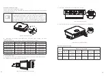
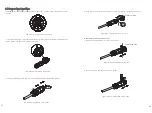
Secure the wall mount as shown, do not let the screws flush with the wall, instead expose 

2 to 4 mm.

fig5.7


Wall mount installation diagram

5.3 Installing the inverter

Note: Before installing the inverter, you must first make sure that the wall mount is firmly 
fixed to the wall.
steps:
1. Hang the inverter on the wall mount and keep the inverter balanced when hanging.
2. To ensure that the inverter can be securely attached to the wall, secure the side of the 
inverter with the M5 safety screw on the left.

fig5.8 Inverter wall hanging diagram

Inverter Wiring 6

6.1 Safety

A high voltage in the conductive part of the inverter may cause an 

electric shock. Therefore, when performing any installation work 

on the inverter, make sure that the AC and DC sides of the inverter 

are powered off.

Static electricity may cause damage to the electronic components 

of  the  inverter.  Antistatic  measures  should  be  taken  during  the 

replacement or installation of the inverter.

Moisture and dust penetration can damage the inverter.

Ø

Make sure the cable connector is securely tightened.
If  the  cable  connector  is  not  installed  correctly,  the  inverter 

may  be  damaged  by  moisture  and  dust.  All  warranty  claims  are 

invalid.

Ø

Note

6.2 AC side wiring

Before  making  electrical  connections,  make  sure  that  the  DC 
switch of the inverter is in the "OFF" state and that the AC side is 
open,  otherwise  the  high  voltage  of  the  inverter  may  be  life-
threatening.

Ø

Ø

Ø

Each  inverter  must  be  independently  installed  with  an  AC 

circuit breaker, and multiple inverters are prohibited from sharing.

Do not use a single core wire at the inverter output.

Ø

It is forbidden to use aluminum wire as the output cable.
Please  ensure  that  the  output  line  is  well  connected  before 

turning on the inverter. Ignoring the above warnings may damage 

the machine or cause other losses. In this case, the company has 

the right not to carry out the warranty, or bear any responsibility 

and related expenses.

Moisture and dust penetration can damage the inverter.

Make sure the cable connector is securely tightened.
If  the  cable  connector  is  not  installed  correctly,  the  inverter 

may  be  damaged  by  moisture  and  dust.  All  warranty  claims  are 

invalid.

Ø
Ø

Danger

Warning

Note

Residual current protection device:
Since  the  inverter  itself  has  a  high-precision  residual  current  detecting  device,  it  is  not 
recommended  to  install  a  switch  with  leakage  protection  in  the  system.  If  for  some 
special reason, it must be installed with leakage protection between the inverter output 

and  the  grid.  For  the  switch,  please  install  the  B-type  leakage  protection  switch  of 
300mA or more. When multiple leakage protection switches are installed in the system, 
the  zero  line  sharing  is  prohibited.  Otherwise,  the  leakage  protection  function  may  be 
triggered by mistake, causing the switch to trip.

Содержание MID 10KTL3-X

Страница 1: ...nzhen P R China No 28 Guangming Road Shiyan Street Bao an District Shenzhen P R China 86 755 2747 1942 www ginverter com www ginverter com T E W service ginverter com service ginverter com 86 755 2747...

Страница 2: ...2 1 Foreword 2 2 Applicable personnel 2 3 Product overview and features 2 4 Safety instructions 1 1 Validity 1 2 Target Group 1 3 Additional information 3 Product Description 4 Unpacking and Inspecti...

Страница 3: ...ubleshooting 7 Debugging 14 Specification 8 1 Normal mode 8 2 Failure mode 8 3 Shutdown mode 9 1 Boot display 9 2 OLED display wake up 9 3 Touch operation 11 1 Start the inverter 11 2 Shut down the in...

Страница 4: ...refully before using this product Any changes to this manual by Growatt New Energy will not be notified to the user 2 2 Applicable Personnel The inverter must be installed by a professional electricia...

Страница 5: ...V modules Otherwise in the sunlight the voltage at the component terminals is high which poses a personal danger Make sure that the input DC voltage does not exceed 550V under any circumstances Higher...

Страница 6: ...t operating state of the inverter red fault green normal operation Flashing red light warning Flashing green light Update program 3 2 Dimensions Size and weight Model Height H Width W Depth D Weight M...

Страница 7: ...nverter for a long time refer to the specifications in Chapter 12 for the weight of the inverter The installation location must match the size of the inverter Do not install the inverter on a building...

Страница 8: ...Installation Environment Make sure that the inverter is installed in a suitable place and is not allowed to be installed in a closed box fig5 4 Closed box In order to reduce the inverter load and ext...

Страница 9: ...h of the inverter is in the OFF state and that the AC side is open otherwise the high voltage of the inverter may be life threatening Each inverter must be independently installed with an AC circuit b...

Страница 10: ...er model Switch specification Inverter model Switch specification MID 6KTL3 XL 25A 127V MID 8KTL3 XL 32A 127V MID 10KTL3 XL 40A 127V MID 11KTL3 XL 40A 127V MID 12KTL3 XL 50A 127V MID 10KTL3 X 32A 230V...

Страница 11: ...PV ground please turn on the low frequency isolation transformer after the output is connected otherwise the inverter will be damaged If it is measured that there is a stable non zero DC voltage betw...

Страница 12: ...allation instructions 2 Push the threaded sleeve into the socket and tighten the waterproof gland fig6 9 Quick installation instructions Ka 3 Dock the client to the inverter plug until both are tightl...

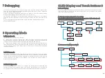
Страница 13: ...real time When the inverter monitors any unexpected conditions such as system failure and inverter failure the fault information will be displayed on the display In the fault mode the inverter indica...

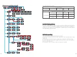
Страница 14: ...ic CT Off grid setting Enable Country Region VDE0126 Country Region VDE0126 Country Region G99 Country Region N4105 Country Region G98 Country Region Ireland Country Region EN50438 Country Region Belg...

Страница 15: ...er 2 Close the DC switch when the input PV voltage is higher than 250Vdc and the inverter will start automatically Start and Shut Down the Inverter 11 11 1 Start the inverter 11 2 Shut down the invert...

Страница 16: ...ew fan 5 Reinstall the fan mounting plate and inverter Troubleshooting 13 PV inverters sometimes do not work properly we recommend the following solutions to eliminate common faults The table below he...

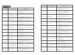
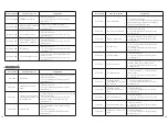
Страница 17: ...anufacturer 13 2 Syetem error 13 2 1 Warning code Warning Code Fault Discription Suggestion Warning 300 No Utility 1 Please confirm grid is lost or not 2 If error message still exists contact manufact...

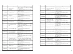
Страница 18: ...r 3 If error message still exists contact manufacturer Error Code Fault Discription Suggestion Error 300 AC V Outrange 1 Check grid voltage 2 If the error message still exists despite the grid voltage...

Страница 19: ...art inverter 2 If error message still exists contact manufacturer Error 414 EEPROM fault 1 Restart inverter 2 If error message still exists contact manufacturer Error 415 Internal power test fail PV P...

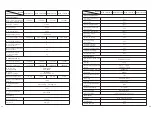
Страница 20: ...ctor 0 8Leading 0 8Lagging THDi 3 AC grid connection type 3W PE 3W N PE Efficiency Max efficiency 98 65 Euro eta 98 3 Specifications Model MID 6KTL3 XL MID 8KTL3 XL MID 10KTL3 XL MID 11KTL3 XL MID 12K...

Страница 21: ...0 8Leading 0 8Lagging THDi 3 AC grid connection type 3W N PE Efficiency Max efficiency 98 65 Euro eta 98 3 Specifications Model MID 10KTL3 X MID 12KTL3 X MID 15KTL3 X MID 17KTL3 X Protection devices D...

Страница 22: ...ng 0 8Lagging THDi 3 AC grid connection type 3W N PE Efficiency Max efficiency 98 65 Euro eta 98 3 Specifications Model MID 20KTL3 X MID 22KTL3 X MID 25KTL3 X Protection devices DC reverse polarity pr...

Страница 23: ...ing the defective equipment The cost of installing or reinstalling a faulty device should also be explicitly excluded from other related logistics and processing costs associated with warranty claims...

Отзывы: