


1
D
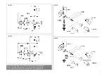
Installation
Maßzeichnungen auf Klappseite I beachten!
1. Waagerechten Mauerdurchbruch Ø 35mm herstellen,
siehe Klappseite II, Abb. [1].
2. Rosette (A) und Isolierung (B) über Armaturenkörper (C)
schieben, siehe Abb. [2].
3.
Armaturenkörper mit Isolierung waagerecht oder mit
leichtem Gefälle zum Armaturenkörper in das Bohr-
loch einsetzen
.
4. Löcher für Rosette (A) bohren, siehe Abb. [3].
5. Dübel (A1) einsetzen und Rosette (A) mit Schrauben (A2)
befestigen, siehe Abb. [4].
6. Oberteil (D), Spindel (E) und Dichtkegel (F) mit Steck-
schlüssel 17mm aus dem Armaturenkörper (C) heraus-
schrauben, siehe Abb. [5].
7. Wasseranschluss mit 1/2" Außengewinde oder Ø 15mm
Cu-Rohr herstellen, siehe Abb. [6].
8. Rosette (A) mit Gewindestift (G) mit Innensechskant-
schlüssel 3mm auf dem Armaturenkörper (C) fixieren,
siehe Abb. [7].
9. Dichtkegel (F) mit Spindel (E) in den Armaturenkörper (C)
stecken und Oberteil (D) einschrauben, siehe Abb. [8].
10. Griff bzw. Kappe montieren, siehe Abb. [9].
Nach jedem Schließen der Armatur läuft für einige Sekun-
den Wasser nach, da sich die Armatur entleeren muss.
Angeschlossene Schläuche immer offen halten und leer
laufen lassen! Zu Beginn der Frostperiode Schläuche un-
bedingt abnehmen!
Wartung
Alle Teile prüfen, reinigen, evtl. austauschen und mit Spezial-
armaturenfett einfetten.
Wasserzufuhr absperren!
I. Austausch des Oberteils
, siehe Abb. [10].
1. Griff bzw. Kappe demontieren
2. Oberteil (D) mit Steckschlüssel 17mm herausschrauben.
3. Gewindestift (H) mit beiliegendem Innensechskantschlüssel
lösen und Oberteil (D) abziehen.
4. Oberteil (D) kompl. austauschen.
II. Rohrbelüfter (I) und Belüfterkegel (J) ausschrauben
und reinigen
, siehe Abb. [10].
Montage in umgekehrter Reihenfolge.
Ersatzteile
,
siehe Klappseite I ( * = Sonderzubehör).
Pflege
Die Hinweise zur Pflege sind der beiliegenden Pflegeanleitung
zu entnehmen.
GB
Installation
Refer to the dimensional drawings on fold-out page I.
1. Make horizontal hole through the wall with a diameter
of 35mm, see fold-out page II, Fig. [1].
2. Push escutcheon (A) and insulation (B) over fitting
body (C), see Fig. [2].
3.
Insert fitting body with insulation into the hole
horizontally or at a slight downward angle to the
fitting body
.
4. Drill holes for escutcheon (A), see Fig. [3].
5. Insert plugs (A1) and fasten escutcheon (A) with
screws (A2), see Fig. [4].
6. Unscrew headpart (D) with spindle (E) and conical seal (F)
from the fitting body (C) using a 17mm socket wrench,
see Fig. [5].
7. Make water connection with 1/2" external thread
or Ø 15mm copper pipe, see Fig. [6].
8. Fasten escutcheon (A) on the fitting body (C) with set
screw (G) using a 3mm Allen key, see Fig. [7].
9. Push conical seal (F) with spindle (E) into the fitting
body (C) and screw in headpart (D), see Fig. [8].
10. Install handle or cap, see Fig. [9].
Each time the fitting is closed, water will continue to run
for a few seconds because the fitting has to drain. Always
keep connected hoses open and allow to run empty.
At the start of the frost period, always detach hoses.
Maintenance
Inspect and clean all parts, replace as necessary and grease
with special grease.
Shut off water supply!
I. Replacing the headpart,
see Fig. [10].
1. Uninstall handle or cap.
2. Unscrew headpart (D) using a 17mm socket wrench.
3. Loosen set screw (H) using Allen key supplied and pull off
headpart (D).
4. Replace complete headpart (D).
II. Unscrew and clean pipe vent (I) and vent cone (J)
,
see Fig. [10].
Reassemble in reverse order.
Replacement parts,
see fold-out page I
( * = special accessories).
Care
For directions on care, refer to the accompanying
Care Instructions.
Содержание Eggeman Eurotec 41 210
Страница 3: ...II 7 A G 3mm C 8 D E F 17mm C 10 D H I J 9 2 A B C 1 5 17mm D E F C 3 A 8 4 A1 A2 A 6...
Страница 18: ......