


8
OM-DEES(T)-40(C,A,C2T™) Domestic
CLEANING CORE PROBE
Remove all food soil from core probe by wiping entire core probe and cable
assembly with warm detergent solution and a clean cloth. Remove detergent
solution by wiping core probe and cable assembly with clean rinse water and a
cloth. Allow core probe and cable assembly to air dry. Do not immerse core probe.
Hand wash only and immediately let air dry.
MAINTENANCE
WARNING: AVOID ANY EXPOSURE TO THE STEAM BLOWING OUT OF THE PRESSURE
RELIEF VALVE. SEVERE BURNS CAN RESULT ON EXPOSED SKIN. FAILURE
TO CHECK PRESSURE RELIEF VALVE OPERATION PERIODICALLY COULD
RESULT IN PERSONAL INJURY AND/OR DAMAGE TO EQUIPMENT.
CAUTION: KEEP GREASE AWAY FROM ELECTRICAL PARTS LOCATED NEAR THE
GEARS.
WARNING: TO AVOID INJURY, READ AND FOLLOW ALL PRECAUTIONS STATED ON THE
LABEL OF THE WATER TREATMENT COMPOUND.
WARNING: USE OF ANY REPLACEMENT PARTS OTHER THAN THOSE SUPPLIED BY
THE MANUFACTURER OR THEIR AUTHORIZED DISTRIBUTORS CAN CAUSE
INJURY TO THE OPERATOR AND DAMAGE TO THE EQUIPMENT AND WILL
VOID ALL WARRANTIES.
CAUTION: INSURE ELECTRICAL POWER IS REMOVED AND THE GAS IS TURNED OFF AT
THE SHUTOFF VALVE PRIOR TO PERFORMING ANY MAINTENANCE ON THIS
KETTLE.
WARNING: THIS KETTLE IS DESIGNED TO BE WATER RESISTANT. FAILURE TO FOLLOW
PROPER MAINTENANCE PROCEDURES MAY VOID THE WARRANTY.
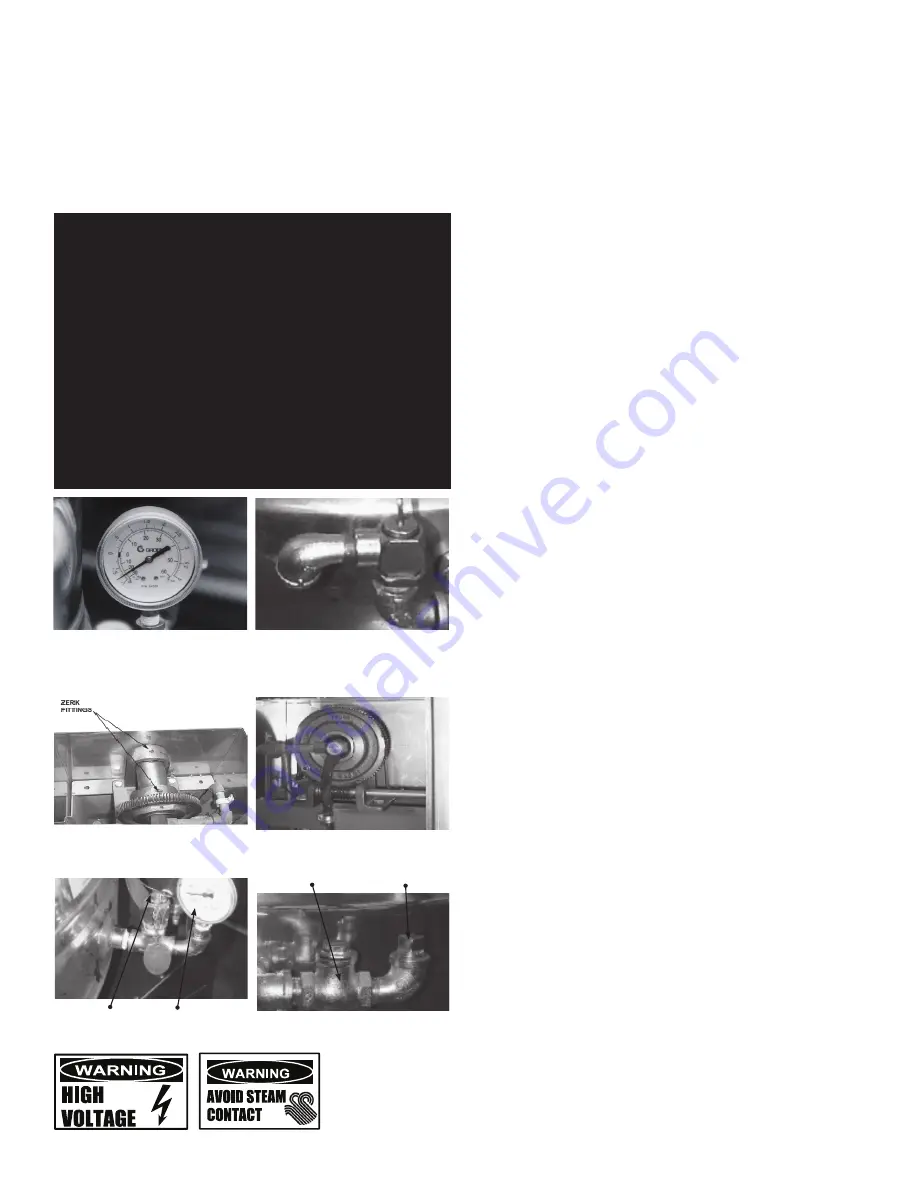
The pressure gauge should show a vacuum of 20 to
30 inches when the kettle is cold.
The open end of the pressure relief valve
elbow must face downward.
Add grease through Zerk Fittings.
Liberally grease the wheel where
it contacts the worm gear.
Safety Valve
Pressure Gauge
Test the safety valve at least twice monthly.
Check Valve
Pipe Plug
PERIODIC MAINTENANCE
NOTICE: Contact an authorized representative when repairs are required.
A Maintenance & Service Log is provided at the back of this manual. Each time
maintenance is performed on your kettle, enter the date on which the work was
done, what was done, and who did it. Keep this manual on file and available
for operators to use. Periodic inspection will minimize equipment down time and
increase the efficiency of operation. The following points should be checked:
[BY OPERATOR]
1. Check the pressure/vacuum gauge every day. The gauge should show a
vacuum of 20 to 30 inches, when the kettle is cold. If it does not, see “Jacket
Vacuum” in this manual.
2. Also check the jacket water level every day. It should be between the marks
on the gauge glass. If the level is low, see “Jacket Filling and Water Treatment”
in this manual.
3. Carefully test the pressure relief valve at least twice each month. With the
kettle operating at 15 psi (105 kPa),pull the test lever and let it snap back to its
closed position. If there is little discharge (mostly air), and the pressure gauge
drops back to zero PSI, allow the pressure to build back to five PSI and repeat
the procedure. (Tip: Using a screwdriver or other implement to pull the ring will
help you avoid contact with the steam.
[BY SERVICE TECHNICIAN]
4. Electrical wiring should be kept securely connected and in good condition.
5. The inside of the support housing should be kept clean.
6. The gear housing has fittings for lubrication of moving parts. The gears do not
run in oil, so periodic lubrication with grease is necessary.
7. Frequency of lubrication depends on operating conditions, but it should be
done at least once every six months.
8. Use a #2 grade LGI lithium grease to add grease through Zerk fittings on gear
housing until it flows out of the bearings around the trunnion shaft.
9. Place liberal amounts of grease on the gear to cover the arc that is in contact
with the worm gear.
10. Keep electrical wiring and connections in good condition.
11. Keep the inside of the control console clean and dry.
JACKET VACUUM/REMOVING AIR FROM JACKET
When the kettle is cold, a positive pressure reading on the pressure/vacuum gauge
or a reading near zero indicates that there is air in the jacket. Air in the jacket acts
as an insulator, and slows kettle heating.
To remove air:
1. Start the unit. (Be sure there is water or product in the kettle when heating).
2. When the pressure/vacuum gauge reaches a positive pressure reading of five
PSI, release the trapped air and steam by pulling up the safety valve ring for
about five seconds. Repeat this step three or four times. Then let the pull ring
snap back into the closed position.
3. If there is little discharge (mostly air), and the pressure gauge drops back to
zero PSI, allow the pressure to build back to five PSI and repeat the procedure.
4. Once steam has been vented from the jacket as described in b, above, remove
the hot water from the kettle and replace it with cold. This will condense steam
in the kettle jacket, and the pressure gauge should show a reading of 20 to
30 inches mercury (Hg) below zero. If it does not, or if the vacuum is leaking
down, contact an authorized service agency to correct the problem.
PRESSURE RELIEF VALVE
At least twice a month, test the pressure relief valve. Test the valve with the kettle
operating at 15 PSI (105 kPa), by holding the test ring for at least five seconds. Then
release the ring and permit the valve to snap shut. If the ring does not activate, if
there is no discharge, or if the valve leaks, stop using the kettle immediately and
contact a authorized service representative.
Содержание DEE/4-20 A
Страница 11: ...11 OM DEES T 40 C A C2T Domestic Parts List...
Страница 12: ...12 OM DEES T 40 C A C2T Domestic Parts List...
Страница 14: ...14 OM DEES T 40 C A C2T Domestic Wiring Diagram For Classic Control Models...
Страница 15: ...15 OM DEES T 40 C A C2T Domestic Wiring Diagram For Advanced Cook2Temp Control Models...


