Model T32002 (Mfd. Since 02/20)
-23-
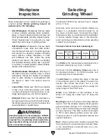
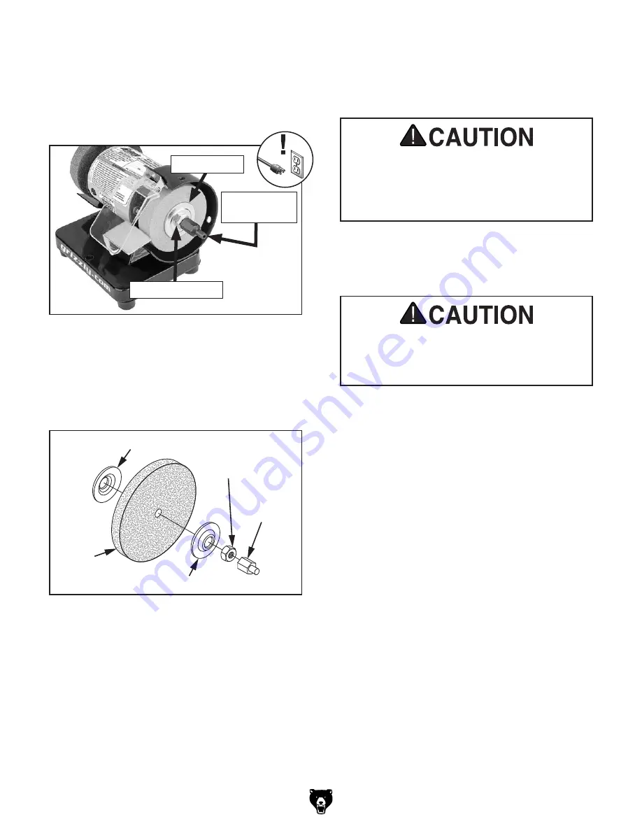
Figure 14. Assembly order for wheel installation.
Outer Flange
Inner Flange
Hex Nut
Wheel
Standoff
Stud
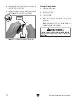
Figure 13. Outer wheel guard removed to
access grinding wheel.
Outer Flange
M8-1.25 Hex Nut
4. Remove outer wheel flange (see Figure 14).
5. Remove grinding wheel from spindle (see
Figure 14).
8. Re-assemble outer wheel guard using hard-
ware removed in
Step 2.
9. While standing to side of the machine, turn
grinder
ON and run new grinding wheel for at
least 1–2 minutes before standing in front of
it. This helps protect you if wheel has internal
damage that will cause it to fly apart from
centrifugal force of rotation.
— If grinder runs smoothly, grinding wheel
may now be used.
— If wheel appears to wobble, grinder
vibrates excessively, or any other unsafe
condition appears with new wheel, stop
grinder and refer to
Troubleshooting on
Page 29.
Warped wheel flanges can contribute to
grinding wheel breaking and flying apart.
Never use warped wheel flanges. Always
check flanges before re-installing grinding
wheel.
6. Verify the flatness of the inner and outer
flanges by placing them on a level surface. If
either flange is warped or damaged, replace
it.
3. Remove M8-1.25 standoff stud and hex nut
(see
Figure 13).
Tip: Hold grinding wheel with free hand to
stop spindle from turning while removing hex
nut.
M8-1.25
Standoff Stud
Overtightening grinding wheel can stress
and crack wheel. Cracked wheel can become
deadly projectiles when machine is turned
on.
7. Mount new grinding wheel as shown in
Figure 14. Tighten M8-1.25 hex nut and
standoff stud snugly but do not over-tighten.
Содержание T32002
Страница 36: ......

