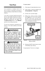
background image

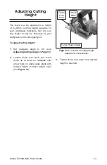
Figure 13. Location of cutting height 

adjustment components.

Model T31999 (Mfd. Since 02/20)

-17

-

Arrow

Mark

Fence Height Scale

Fence 

Lock

Knob

Adjusting Cutting 

Height

The  fence  can  be  adjusted  to  a  height 
of  0–40mm.  Cutting  height  depends  on 
your  workpiece  thickness.  Set  the  cut-
ting  height  to  half  the  thickness  of  your 
workpiece for the strongest joint.

To adjust cutting height:

1.  Set  faceplate  angle  to  90°  (see 

Adjusting Cutting Angle on Page 16).

2.  Loosen  fence  lock  knob  and  move 

fence  up  or  down  on  faceplate  until 
arrow mark on angle scale aligns with 
desired  height  on  fence  height  scale 
(see 

Figure 13).

3.  Tighten fence lock knob once desired 

height is reached.

Содержание T31999

Страница 1: ...INC WARNING NO PORTION OF THIS MANUAL MAY BE REPRODUCED IN ANY SHAPE OR FORM WITHOUT THE WRITTEN APPROVAL OF GRIZZLY INDUSTRIAL INC KS20992 PRINTED IN CHINA MODEL T31999 BISCUIT JOINER OWNER S MANUAL For models manufactured since 02 20 V1 03 20 ...

Страница 2: ...ng grinding tool integrity and the usage of personal protective equipment The manufacturer will not be held liable for injury or property damage from negligence improper training machine modifications or misuse Some dust created by power sanding sawing grinding drilling and other construction activities contains chemicals known to the State of California to cause cancer birth defects or other repr...

Страница 3: ...ntory 12 Assembly 13 Dust Collection 13 Test Run 14 SECTION 5 OPERATIONS 15 Adjusting Depth of Cut 15 Adjusting Cutting Angle 16 Adjusting Cutting Height 17 Workpiece Preparation 18 Cutting Biscuit Grooves 19 Gluing Biscuits 19 Changing Blade 20 SECTION 6 ACCESSORIES 22 SECTION 7 MAINTENANCE 23 Cleaning 23 Lubrication 23 Replacing Brushes 24 SECTION 8 SERVICE 25 Troubleshooting 25 SECTION 9 PARTS ...

Страница 4: ...under stand this owner s manual BEFORE using machine TRAINED OPERATORS ONLY Untrained operators have a higher risk of being hurt or killed Only allow trained supervised people to use this power tool When tool is not being used disconnect power and store in out of reach location to prevent unauthorized use especially around children Make workshop kid proof DANGEROUS ENVIRONMENTS Do not use tools in...

Страница 5: ...S Use right tool for job and do not force it It will do job safer and better at rate for which it was designed SECURING WORKPIECE When required use clamps or vises to secure workpiece This protects hands and frees both of them to operate tool GUARDS COVERS Guards and cov ers reduce accidental contact with mov ing parts or flying debris Ensure they are properly installed undamaged and working corre...

Страница 6: ...n place and operating correctly before each cut STARTING AND STOPPING CUTS Allow blade to reach full speed before cutting Always allow blade to come to a complete stop before setting tool down MAINTAIN CONTROL OF TOOL Hold tool with both hands and do not allow the Biscuit Joiner base to shift while perform ing plunge cuts Serious cuts amputation or death can occur from contact with rotating saw bl...

Страница 7: ...02 20 5 SECTION 2 INTRODUCTION We are proud to offer this manual with your new Model T31999 Biscuit Joiner We ve made every effort to be exact with the instructions specifications drawings and photographs of the joiner we used when writing this manual However sometimes we still make an occasional mistake Also owing to our policy of continuous improvement your biscuit joiner may not exactly match t...

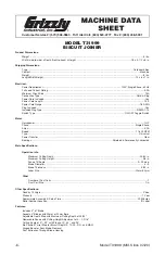
Страница 8: ...hielded Permanently Lubricated Main Specifications Operation Info Maximum Cutting Depth 23 32 in Maximum Cutting Height 3 4 in Fence Tilt Angle 0 90 deg Blade Diameter 4 in Blade Thickness 5 32 in Arbor Size 20mm 22mm Other Number of Dust Ports 1 Dust Port Size 1 in Other Specifications Country Of Origin China Warranty 1 Year Approximate Assembly Setup Time 20 Minutes Serial Number Location ID Lab...

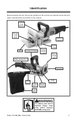
Страница 9: ...miliar with the names and locations of the controls and features shown below to better understand the instructions in this manual Spindle Lock Button Fence Lock Knob Angle Scale ON OFF Switch Dust Port Dust Bag Sliding Base Depth Indicator Depth Stop Faceplate Fence Angle Lock Fence Height Scale Fence Auxiliary Handle Blade Access Knob ...

Страница 10: ...le D Fence Height Scale Indicates dis tance between center of blade and bottom of fence E Angle Scale Indicates angle of cut F ON OFF Switch Starts and stops motor Tool will remain running while switch is held until released G Dust Port Connects dust extraction system to blade housing and prevents dust build up during cutting operations H Sliding Base Houses blade Spring action retracts blade afte...

Страница 11: ...t the maximum amount of amps that the machine will draw If the machine is overloaded it will draw additional amps beyond the full load rating If the machine is overloaded for a sufficient length of time damage overheating or fire may result especially if connected to an undersized circuit To reduce the risk of these hazards avoid overloading the machine dur ing operation and make sure it is connec...

Страница 12: ...sure the cords are rated for outdoor use Outdoor use cords are marked with a W A or a W to signify their rating Always check to make sure that the exten sion cords are in good working order and free of any type of damage such as exposed wires cuts creased bends or missing prongs Extension cords cause voltage drop which may damage electrical components and shorten motor life Voltage drop increases ...

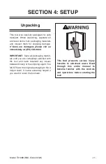
Страница 13: ...port When unpacking separate all enclosed items from packaging materials and inspect them for shipping damage If items are damaged please call us immediately at 570 546 9663 IMPORTANT Save all packaging materi als until you are completely satisfied with the tool and have resolved any issues between Grizzly or the shipping agent You MUST have the original packaging to file a freight claim It is als...

Страница 14: ...y Model T31999 Mfd Since 02 20 12 The following is a list of items shipped with your tool Before beginning setup lay these items out and inventory them If any non proprietary parts are missing e g a nut or a washer we will gladly replace them or for the sake of expediency replacements can be obtained at your local hardware store Box 1 Figures 4 5 Qty A Biscuit Joiner 1 B Dust Bag 1 C Fence 1 D Hex...

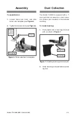
Страница 15: ...Figure 6 2 Tighten fence lock knob see Figure 6 Fence Faceplate Fence Lock Knob Assembly Dust Collection The Model T31999 is equipped with a 1 dust port that can attach to a dust collec tion system not included or the included dust bag To install dust bag 1 Push plastic end of dust bag into dust port as shown in Figure 7 Dust Port Dust Bag 2 Verify dust bag is closed before operat ing tool ...

Страница 16: ...nging Blade on Page 20 3 Connect tool to power supply 4 While firmly holding auxiliary handle see Figure 8 in one hand squeeze ON OFF switch with opposite hand Motor should run smoothly and without unusual problems or noises 5 Release ON OFF switch Motor should immediately stop running Congratulations Test run is complete ON OFF Switch Auxiliary Handle Test Run Once assembly is complete test run t...

Страница 17: ...asses and a respirator when oper ating this tool Biscuit Material Thickness mm Cut Depth mm Depth Indicator Marking 0 4 8 0 10 4 10 10 20 4 12 5 20 Simplex 4 13 S Duplex 4 15 D N A N A 18 MAX Figure 9 Biscuit cut depth and depth scale marking table Figure 10 Depth indicator aligned with arrow mark Model T31999 Mfd Since 02 20 15 SECTION 5 OPERATIONS Adjusting Depth of Cut The biscuit joiner can be...

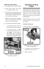
Страница 18: ...surement equals 10mm the cutting depth is properly calibrated If measurement does not equal 10mm loosen depth stop lock nut see Figure 11 and reduce or extend depth stop until measure ment equals 10mm Tighten depth stop lock nut once depth is reached Adjusting Cutting Angle The faceplate can be adjusted between 0 and 90 though 90 is the most common angle of cut for biscuit joining Certain applicat...

Страница 19: ...pends on your workpiece thickness Set the cut ting height to half the thickness of your workpiece for the strongest joint To adjust cutting height 1 Set faceplate angle to 90 see Adjusting Cutting Angle on Page 16 2 Loosen fence lock knob and move fence up or down on faceplate until arrow mark on angle scale aligns with desired height on fence height scale see Figure 13 3 Tighten fence lock knob o...

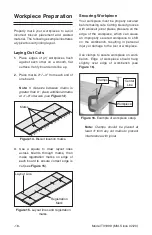
Страница 20: ... greater than 6 place additional marks at 4 6 intervals see Figure 14 3 Use a square to draw layout lines across boards through marks then make registration marks on edge of each board to ensure correct edge is cut see Figure 15 Your workpiece must be properly secured before making cuts Cutting biscuit grooves with a biscuit joiner places pressure on the edge of the workpiece which can cause an im...

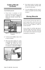
Страница 21: ...al and the glue manufacturer s instructions 4 Once blade reaches full depth slide joiner body backward allowing blade to retract into base plate 5 Turn joiner OFF and wait for motor to come to a complete stop before setting tool down To cut biscuit grooves 1 Place fence on workpiece so front groove and rear groove line up with layout line as shown in Figure 17 Make sure faceplate contacts edge of ...

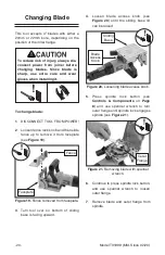
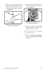
Страница 22: ...nge 3 Turn tool over so bottom of sliding base is facing upward 4 Loosen blade access knob see Figure 20 until the sliding base lid can be raised Sliding Base Blade Access Knob Faceplate Fence 5 Press spindle lock button see Controls Components on Page 8 and use spanner wrench to turn outer flange until spindle lock engages spindle see Figure 21 6 Continue to press spindle lock button and use span...

Страница 23: ...bores flip inner flange over before installing new blade to accommodate change in bore size see Figure 22 8 Install new blade verify teeth face cor rect direction for rotation of spindle as shown in Figure 23 9 Place outer flange on spindle press spindle lock button and tighten outer flange with spanner wrench 10 Close sliding base lid and tighten blade access knob 11 Install fence to desired heig...

Страница 24: ...hese helpful little pieces of beechwood stay in their original shape and size until they soak up water based glues resulting in a tighter wood joint This variety pack includes 500 biscuits of size 20 250 of size 10 and 250 of size 0 order online at www grizzly com or call 1 800 523 4777 H1165 Polyurethane Glue 36 oz This polyurethane glue is the finest available for bonding wood stone metal cerami...

Страница 25: ...cularly from around the blade slot on the sliding base Never blow off the tool with compressed air as this could force wood chips deeper into the motor vents Use a clean cloth to wipe away any dust remaining after each operation Note DO NOT use caustic cleaners on plastic parts If dry cleaning is insufficient a mild detergent on a damp cloth is recom mended Keep water away from tool at all times L...

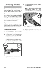
Страница 26: ...lt carefully use a small screwdriver to push down on the brush holder tabs to release them Replacing Brushes This tool is equipped with a universal motor that uses two carbon brushes to transmit electrical current inside the motor These brushes are considered to be regu lar wear items or consumables that will need to be replaced during the life of the motor The frequency of required replace ment i...

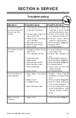
Страница 27: ...r powered 1 Workpiece material not suit able for tool 2 Tool undersized for task 3 Dust bag at fault 4 Blade at fault 5 Motor brushes at fault 6 Motor bearings at fault 7 Motor overheated 8 Motor at fault 1 Only cut wood ensure mois ture is below 20 2 Reduce feed rate depth of cut 3 Empty bag clear dust port 4 Remove replace Page 20 5 Remove replace Page 24 6 Test repair replace 7 Clean motor let ...

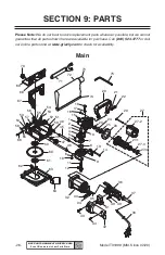
Страница 28: ...4 65 66 67 68 69 70 71 72 73 75 74 Model T31999 Mfd Since 02 20 26 BUY PARTS ONLINE AT GRIZZLY COM Scan QR code to visit our Parts Store SECTION 9 PARTS Main Please Note We do our best to stock replacement parts whenever possible but we cannot guarantee that all parts shown here are available for purchase Call 800 523 4777 or visit our online parts store at www grizzly com to check for availabilit...

Страница 29: ...99055 E CLIP 6MM 19 PT31999019 SNAP RING 5MM 56 PT31999056 ANGLE LOCK LEVER 20 PT31999020 AUXILIARY HANDLE 57 PT31999057 COUPLING NUT M6 1 X 12 21 PT31999021 FLAT WASHER 8MM 58 PT31999058 CARRIAGE BOLT M6 1 X 20 22 PT31999022 CAP SCREW M8 1 25 X 14 59 PT31999059 INNER SPINDLE FLANGE 23 PT31999023 PINION GEAR 60 PT31999060 CIRCULAR BLADE 4 X 6T X 5 32 24 PT31999024 BALL BEARING 629ZZ 61 PT31999061 ...

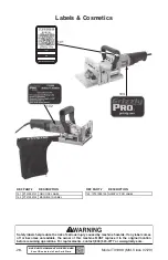
Страница 30: ...he original location before resuming operations For replacements contact 800 523 4777 or www grizzly com 102 103 101 REF PART DESCRIPTION REF PART DESCRIPTION 101 PT31999101 QR CODE LABEL 103 PT31999103 GRIZZLY PRO LABEL 102 PT31999102 MACHINE ID LABEL Model T31999 Mfd Since 02 20 28 BUY PARTS ONLINE AT GRIZZLY COM Scan QR code to visit our Parts Store Labels Cosmetics ...

Страница 31: ...contingent special or consequential damages arising from the use of our products The manufacturers reserve the right to change specifications at any time because they constantly strive to achieve better quality equipment We make every effort to ensure that our products meet high quality and durability standards and we hope you never need to use this warranty In the event you need to use this warra...

Страница 32: ......
Отзывы: