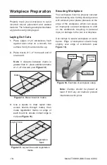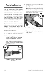
Figure 11. Location of cutting depth
adjustment components.
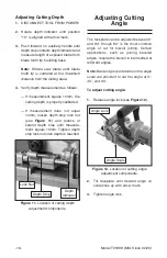
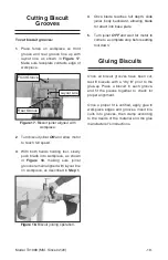
Figure 12. Location of cutting angle
adjustment components.
Model T31999 (Mfd. Since 02/20)
-16
-
Depth
Indicator
Lock Nut
Depth Stop
1. DISCONNECT TOOL FROM POWER!
2. Rotate depth indicator until position
"10" is aligned with arrow mark.
3. Push forward on auxiliary handle until
depth stop contacts depth indicator and
measure length of exposed blade from
blade tooth tip to sliding base.
Note:
Rotate saw blade until blade
tooth tip is centered at the maximum
distance from the sliding base.
4. Verify depth measurement as follows:
— If measurement equals 10mm, the
cutting depth is properly calibrated.
— If measurement
does not
equal
10mm, loosen depth stop lock nut
(see
Figure 11) and reduce or
extend depth stop until measure-
ment equals 10mm. Tighten depth
stop lock nut once depth is reached.
Adjusting Cutting
Angle
The faceplate can be adjusted between 0°
and 90°, though 90° is the most common
angle of cut for biscuit joining. Certain
applications, such as joining beveled
edges, require the biscuit to be inserted at
different angles.
Note:
Ball and groove detents on the angle
scale are provided to set the angle at 0°,
45°, and 90°.
To adjust cutting angle:
1. Release angle lock (see Figure 12).
Angle Lock
Angle Scale
2. Tilt faceplate until desired angle on
scale lines up with arrow mark.
3. Tighten angle lock.
Adjusting Cutting Depth
Содержание T31999
Страница 32: ......

