-16-
Model T28522 (Mfd. Since 09/18)
Adjusting Setback
Before you begin any bending operation, consider
the differences of sheet metal gauges when try-
ing to achieve either sharp or rounded bends, and
allow for the differences by adjusting the setback.
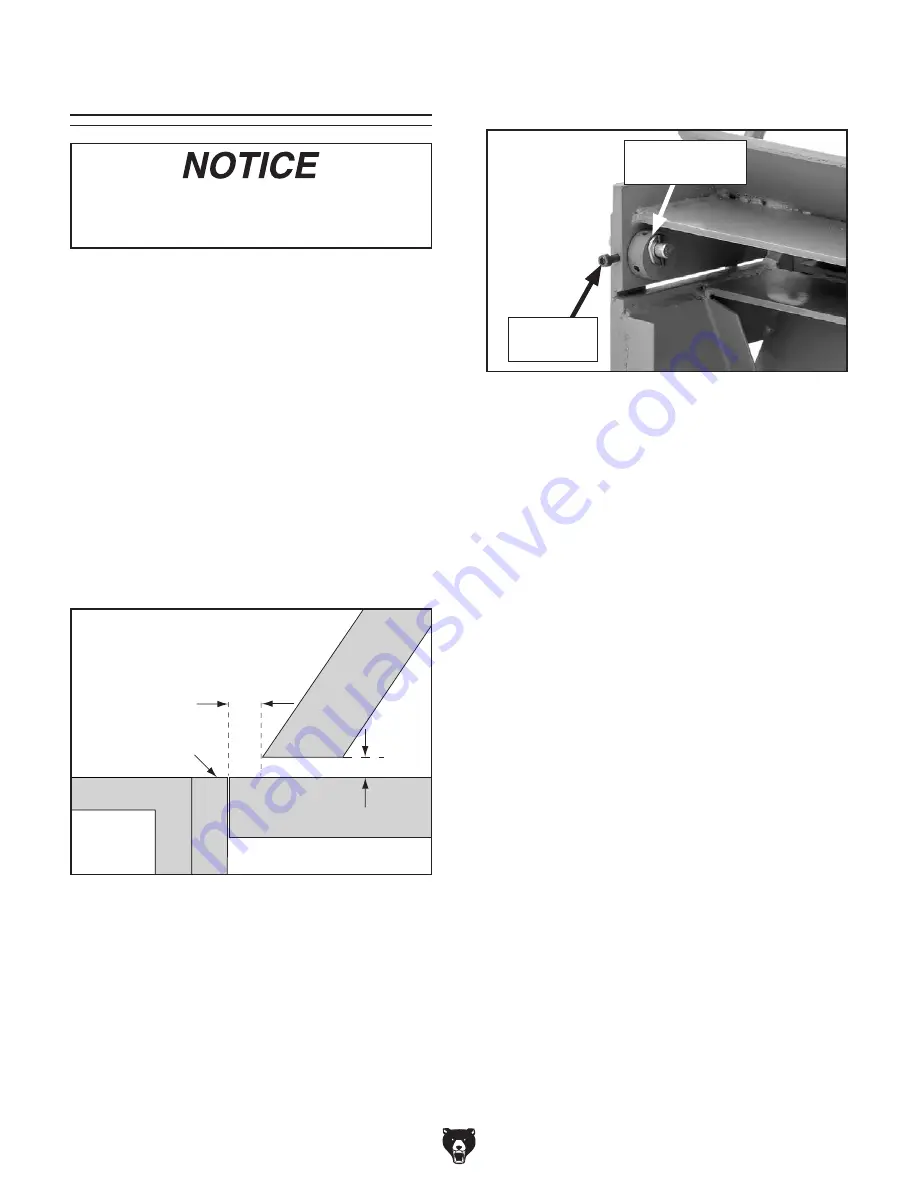
Setback is the distance from the forward edge
of the fingers to the edge of the bending leaf,
as shown in
Figure 12. The setback distance is
determined by the gauge of the workpiece mate-
rial and the desired radius of the bend.
Setback is normally adjusted 1
1
⁄
2
times the thick-
ness of 22 gauge and thinner workpieces, and
two times the thickness of workpieces thicker than
22 gauge. (Refer to material gauge capacities on
the
Machine Data Sheet on Page 5.)
Figure 12. Determining setback distance for
workpieces 22 gauge and thinner.
Bending
Block
Clamping
Surface
Edge View
A
1
1
/
2
x A
Bending
Leaf
Setback
Distance
Finger
4. Rotate both setback wheels until desired set-
back distance is achieved.
Note: Setback wheels are eccentric. Turning
them one full turn will bring clamping leaf
back to its original position.
Tip: If you find it hard to turn setback wheels
with your fingers, insert a hex wrench into the
holes on edges of wheels to gain leverage.
5. Lower clamping fingers onto clamping sur-
face and check setback distance.
6. If necessary, repeat Steps 1–4 until desired
setback is achieved.
7. Check finger alignment (refer to Aligning
Fingers on Page 15).
You must include the thickness of folded
edges or joints when determining the prop-
er setback, or the brake may be damaged.
Item(s) Needed:
Qty
Hex Wrench 5mm .............................................. 1
To adjust setback:
1. Determine setback required for bend.
2. Raise clamping fingers about
1
⁄
2
" off of clamp-
ing surface.
Figure 13. Location of setback wheel and cap
screw.
Cap Screw
(1 of 2)
Setback Wheel
(1 of 2)
3. Loosen cap screws that secure setback
wheels (see
Figure 13).
adjusting setback


