Grizzly T10824 Скачать руководство пользователя страница 21

Model T10824 (Mfd. Since 07/14)

-21-

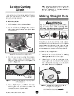
3.  Align  start  cut-point  with  rear  cutting  indica-

tor arrow (see 

Figure 18). This arrow marks 

maximum  rear  cutting  distance  blade  will 
travel when fully extended.

The 24" Rail Track (Model T10825) and Accessory 
Pack  (Model  T27044)  are  available  for  purchase 
separately through our catalog and on-line.

Using your saw with the rail track allows for quick 
and  precise  cuts  with  minimal  setup  time.  Both 
straight cuts and plunge cuts can be made in con-
junction with the rail track.

Note: The bottom of the rail track includes an 
oversized rubber lip that serves as a splinter 
guard. The first time the track saw is used with 
the rail, the saw blade will cut the edge of that lip 
to provide a zero-clearance effect, which will help 
minimize splintering.

To set up saw with rail track:

1.  DISCONNECT SAW FROM POWER!

2.  Place track on workpiece. Orient track so that 

your cut-off will be to right of track.

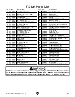
3.  When satisfied with position of rail track, use 

F-clamps to secure it to workpiece, as shown 
in 

Figure 19, and place saw onto rail track.

Using Rail Track

Allow the saw to reach full speed before 

beginning the cut. Doing so will reduce risk 

of kickback, provide better cutting results, 

and reduce stress on the motor.

Rear

Arrow

Center

Arrow

Front

Arrow

Figure 18. Cutting indicator arrows.


Note: The front and rear cutting indicator 
arrows are only accurate when the blade is 
fully extended. If the saw depth gauge is set, 
maximum cutting distance will be less.

4.  Engage  plunge  release  and  lower  blade 

slightly, but without touching workpiece.

5.  To  activate  saw,  engage  safety  button  and 

press 

ON/OFF  trigger  while  holding  plunge 

release.

6.  Lower  blade  into  workpiece  until  set  cutting 

depth  is  reached.  Move  saw  forward  in  an 
even,  steady  motion.  When  front  indicator 
arrow  reaches  stop  point,  the  cut  has  been 
completed.

Figure 19. Rail track clamped to workpiece.

Содержание T10824

Страница 1: ...nufactured since 7 14 COPYRIGHT AUGUST 2014 BY GRIZZLY INDUSTRIAL INC REVISED NOVEMBER 2014 TR WARNING NO PORTION OF THIS MANUAL MAY BE REPRODUCED IN ANY SHAPE OR FORM WITHOUT THE WRITTEN APPROVAL OF...

Страница 2: ...g grinding tool integrity and the usage of personal protective equipment The manufacturer will not be held liable for injury or property damage from negligence improper training machine modifications...

Страница 3: ...ventory 15 Dust Collection 16 SECTION 4 OPERATIONS 17 Blade Selection 17 Changing Blades 17 Setting Cutting Depth 19 Making Straight Cuts 19 Making Plunge Cuts 20 Using Rail Track 21 Adding Rail Track...

Страница 4: ...ll be reflected on our website as soon as complete No list of safety guidelines can be complete Every shop environment is different Always consider safety first as it applies to your individual workin...

Страница 5: ...passes through during a cutting operation Kickback An event in which the tool or workpiece is propelled back towards the operator at a high rate of speed Parallel Being an equal distance apart at eve...

Страница 6: ...kpiece E Depth Scale Indicates maximum depth of cut F Depth Stop Lock Knob Sets maximum depth at which saw blade will plunge G Rail Adjustment Knobs Allow for adjust ment of play in how saw slides alo...

Страница 7: ...2mm arbor hole and is 1 15mm thick A 20 tooth carbide tipped blade is included K Arbor Bolt Holds saw blade in place on the arbor Remove it to change blades Figure 2 Controls and features front view L...

Страница 8: ...ge 16 AWG Plug Type Included NEMA 1 15 Two Prong Polarized Motor Type Universal Horsepower 1 5 HP Voltage 120V Phase Single Phase Amps 10A Speed 28 050 RPM Cycle 60 Hz Main Specifications Blade Specif...

Страница 9: ...Make workshop kid proof DANGEROUS ENVIRONMENTS Do not use tools in areas that are wet cluttered or have poor lighting Operating tools in these areas greatly increases risk of accidents and injury MEN...

Страница 10: ...ebris Make sure they are properly installed undamaged and working correctly CHILDREN BYSTANDERS Keep children and bystanders at a safe distance from the work area Stop using machine if they become a d...

Страница 11: ...porting workpiece with one hand or balancing it on a leg or any other body part USE CORRECT CUTTING DEPTH To minimize exposure spinning blade set the cutting depth so the blade protrudes no more than...

Страница 12: ...autions to help prevent the most common causes of kickback Hold saw firmly with both hands and position arms to help resist kickback forces Always stand to one side of saw when operating never directl...

Страница 13: ...n undersized circuit To reduce the risk of these hazards avoid over loading the machine during operation and make sure it is connected to a power supply circuit that meets the specified circuit requir...

Страница 14: ...utral Hot When using extension cords make sure the cords are rated for outdoor use Outdoor use cords are marked with a W A or a W to signify their rat ing Always check to make sure that the extension...

Страница 15: ...h your machine Before beginning setup lay these items out and inventory them If any non proprietary parts are missing e g a nut or a washer we will gladly replace them or for the sake of expediency re...

Страница 16: ...variables is beyond the scope of this manual Consult an expert or purchase a good dust collection how to book This machine creates substantial amounts of dust during operation Breathing air borne dus...

Страница 17: ...h different materi als see Figure 8 A Coarse Tooth Blade for use with wood and wood based material B Diamond Blade for use with tiles and stone C Abrasive Blade for use with steel D Fine Tooth Blade f...

Страница 18: ...er Flange Outer Flange Blade Dock Washer Arbor Bolt Figure 13 Installation order of blade and related components 8 Pivot saw all the way down then tighten release screw shown in Figure 9 on Page 17 3...

Страница 19: ...its the amount of blade that is exposed during the cutting operation 4 Adjust depth stop so it contacts saw body then retighten lock knob The saw blade will now plunge only to that set point Straight...

Страница 20: ...ngers and hands away from saw blade and out of blade path during opera tion Use clamps to hold workpiece in place if needed Making blind plunge cuts without checking your cutting path for unseen objec...

Страница 21: ...ace track on workpiece Orient track so that your cut off will be to right of track 3 When satisfied with position of rail track use F clamps to secure it to workpiece as shown in Figure 19 and place s...

Страница 22: ...iction see Figure 20 When engaged rail adjustment knobs can help keep saw from lifting off track Figure 20 Location of rail adjustment knobs Rail Adjustment Knobs Additional rail tracks Model T10825 c...

Страница 23: ...nd joined together for longer cuts T27044 Accessory Pack for T10824 Includes rail track connector for extending track two rail clamps for securing track to workpiece and an adjustable stop Figure 25 T...

Страница 24: ...are pre lubricated and sealed Do not attempt to lubricate the saw or saw blade The saw requires dry conditions for proper use Lubrication Blade Always check saw blade for damage or excessive wear befo...

Страница 25: ...e 1 Test repair replace 2 Replace warped bent blade resharpen dull blade 3 Ensure workpiece is properly supported clamped Cuts are rough or wavy workpiece rips or splinters 1 Saw blade is dull 2 Incor...

Страница 26: ...53 54 55 56 57 58 59 60 61 62 63 69 70 64 65 66 64 65 66 67 68 71 72 71 72 73 74 73 74 75 76 77 T10824 Parts Breakdown SECTION 8 PARTS Please Note We do our best to stock replacement parts whenever p...

Страница 27: ...5 9 X 31MM 20 PT10824020 INNER FLANGE 59 PT10824059 POWER CORD 16AWG 2W 72 1 15P 21 PT10824021 BLADE ARBOR 60 PT10824060 CABLE SLEEVE 22 PT10824022 WOODRUFF KEY 4 X 13 61 PT10824061 MOTOR HOUSING 23 P...

Страница 28: ...PT10824102 BOTTOM RUBBER FOAM STRIP 103 PT10824103 ALUMINUM TRACK 24 104 PT10824104 TOP PLASTIC STRIP T27044 Accessory Pack 105 106 107 108 109 REF PART DESCRIPTION 105 PT10824105 LOCK KNOB M10 X 10...

Страница 29: ...metalworker ____ 0 2 Years ____ 2 8 Years ____ 8 20 Years ____20 Years 6 How many of your machines or tools are Grizzly ____ 0 2 ____ 3 5 ____ 6 9 ____10 7 Do you think your machine represents a good...

Страница 30: ...LINE FOLD ALONG DOTTED LINE GRIZZLY INDUSTRIAL INC P O BOX 2069 BELLINGHAM WA 98227 2069 Place Stamp Here Name_______________________________ Street_______________________________ City______________S...

Страница 31: ...shall be tried in the State of Washington County of Whatcom We shall in no event be liable for death injuries to persons or property or for incidental contingent special or consequential damages arisi...

Страница 32: ......

Отзывы: