


Model G0926 (Mfd. Since 11/20)
-17-
Assembly
To assemble machine:
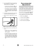
1. Slide head-locking pin into headstock pivot
arm and base (see
Figure 9).
The machine must be fully assembled before it
can be operated. Before beginning the assembly
process, refer to
Needed for Setup and gather
all listed items. To ensure the assembly process
goes smoothly, first clean any parts that are cov-
ered or coated in heavy-duty rust preventative (if
applicable).
Figure 11. Short braces attached to legs.
Short
Braces
Base
Headstock
Pivot Arm
Figure 9. Headstock locked in down position.
2. With help from an assistant, lift bandsaw onto
pair of closely spaced sawhorses or other
suitable support (see
Figure 10).
3. Attach legs to bandsaw with (8) M8-1.25 x 20
hex bolts, 8mm flat washers, 8mm lock wash-
ers, and M8-1.25 hex nuts (see
Figure 10).
Note: Tighten just enough to secure parts.
Final tightening will take place when stand is
fully assembled.
4. Attach short braces to legs with (4) M8-1.25
x 16 carriage bolts, 8mm flat washers, 8mm
lock washers, and M8-1.25 hex nuts (see
Figure 11).
Figure 10. Example of attaching legs to
bandsaw.
Note: Tighten just enough to secure parts.
Final tightening will take place when stand is
fully assembled.
5. Remove bandsaw from sawhorses and
attach long braces to legs with (4) M8-1.25
x 16 carriage bolts, 8mm flat washers, 8mm
lock washers, and M8-1.25 hex nuts (see
Figure 12).
x 4
x 8
Figure 12. Long braces attached to legs.
Long Brace
(1 of 2)
x 4
Head-Locking Pin
Содержание G0926
Страница 56: ......


