-4-
Model G0815 (Mfd. Since 09/18)
Controls &
Components
Refer to
Figures 1–3 and the following descrip-
tions to become familiar with the basic controls
and components of this machine. Understanding
these items and how they work will help you
understand the rest of the manual and stay safe
when operating this machine.
To reduce your risk of
serious injury, read this
entire manual BEFORE
using machine.
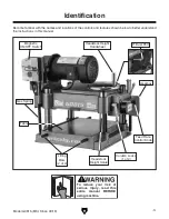
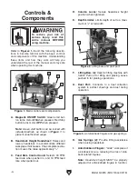
A. Magnetic ON/OFF Switch: Green start but-
ton turns motor
ON when pressed. Red Stop
button turns motor
OFF when pressed.
Note: Green start button can be locked with
included padlock, as shown in
Figure 1, to
prevent unauthorized usage.
B. Headstock Height Handwheel: Raises and
lowers headstock to accommodate different
workpiece thicknesses. One complete revolu-
tion moves the table approximately
1
⁄
8
".
C. Feed Rate Control Knob: Selects 30 FPM
feed rate when pushed in, and 16 FPM feed
rate when pulled out.
Figure 1. Main controls and components.
A
B
C
D
D
E
Figure 2. Lifting bars and dust port.
F
G
F. Lifting Bars (4): Used for lifting machine with
forklift. Pull out for lifting and placing. Leave
pushed in for planing operations.
G. Dust Port: Connects to a dust collection
system to extract shavings and dust during
operation.
Figure 3. Anti-kickback fingers and gas springs.
H. Gas Springs (2): Provide lifting assistance
when raising headstock.
I. Anti-Kickback Fingers: "Grab" workpiece if
a kickback occurs, reducing the risk of kick-
back related injuries.
Note: Headstock height MUST be properly
adjusted for anti-kickback fingers to function.
I
H
D. Column Locks: Secure headstock height
position when tightened.
E. Depth Limiter: Limits depth of cut to a maxi-
mum of
1
⁄
8
" at full width.
Содержание G0815
Страница 56: ......


