background image

-8-

Model G0815 (Mfd. Since 09/18)

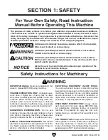
ELECTRICAL EQUIPMENT INJURY RISKS. 

You can be shocked, burned, or killed by touching 

live electrical components or improperly grounded 

machinery. To reduce this risk, only allow qualified 

service  personnel  to  do  electrical  installation  or 

repair work, and always disconnect power before 

accessing or exposing electrical equipment.

DISCONNECT POWER FIRST.  Always  discon-

nect  machine  from  power  supply  BEFORE  mak-

ing  adjustments,  changing  tooling,  or  servicing 

machine.  This  prevents  an  injury  risk  from  unin-

tended  startup  or  contact  with  live  electrical  com-

ponents.

EYE PROTECTION. Always wear ANSI-approved 

safety glasses or a face shield when operating or 

observing  machinery  to  reduce  the  risk  of  eye 

injury or blindness from flying particles. Everyday 

eyeglasses are NOT approved safety glasses.

OWNER’S MANUAL. Read and understand this 

owner’s manual BEFORE using machine. 

TRAINED OPERATORS ONLY. Untrained oper-

ators  have  a  higher  risk  of  being  hurt  or  killed. 

Only  allow  trained/supervised  people  to  use  this 

machine.  When  machine  is  not  being  used,  dis-

connect  power,  remove  switch  keys,  or  lock-out 

machine to prevent unauthorized use—especially 

around children. Make your workshop kid proof!

DANGEROUS ENVIRONMENTS. Do  not  use 

machinery in areas that are wet, cluttered, or have 

poor lighting. Operating machinery in these areas 

greatly increases the risk of accidents and injury.

MENTAL ALERTNESS REQUIRED. Full mental 

alertness is required for safe operation of machin-

ery. Never operate under the influence of drugs or 

alcohol, when tired, or when distracted.

For Your Own Safety, Read Instruction 

Manual Before Operating This Machine

The purpose of safety symbols is to attract your attention to possible hazardous conditions. 

This manual uses a series of symbols and signal words intended to convey the level of impor-

tance of the safety messages. The progression of symbols is described below. Remember that 

safety messages by themselves do not eliminate danger and are not a substitute for proper 

accident prevention measures. Always use common sense and good judgment.

Indicates a potentially hazardous situation which, if not avoided, 
MAY result in minor or moderate injury. It may also be used to alert 
against unsafe practices.

Indicates a potentially hazardous situation which, if not avoided, 
COULD result in death or serious injury.

Indicates an imminently hazardous situation which, if not avoided, 
WILL result in death or serious injury.

Alerts the user to useful information about proper operation of the 
machine to avoid machine damage.

NOTICE

Safety Instructions for Machinery

SECTION 1: SAFETY

Содержание G0815

Страница 1: ... COPYRIGHT FEBRUARY 2016 BY GRIZZLY INDUSTRIAL INC REVISED DECEMBER 2018 MN WARNING NO PORTION OF THIS MANUAL MAY BE REPRODUCED IN ANY SHAPE OR FORM WITHOUT THE WRITTEN APPROVAL OF GRIZZLY INDUSTRIAL INC WK17990 PRINTED IN TAIWAN V2 12 18 Shown with optional stand Model T27650 177335 ...

Страница 2: ...ng grinding tool integrity and the usage of personal protective equipment The manufacturer will not be held liable for injury or property damage from negligence improper training machine modifications or misuse Some dust created by power sanding sawing grinding drilling and other construction activities contains chemicals known to the State of California to cause cancer birth defects or other repr...

Страница 3: ... 4 OPERATIONS 21 Operation Overview 21 Workpiece Inspection 22 Wood Types 22 Planing Tips 23 Cutting Problems 23 Depth of Cut 24 Setting Feed Rate 25 Adjusting Replacing Knives 25 SECTION 5 ACCESSORIES 27 SECTION 6 MAINTENANCE 31 Schedule 31 Cleaning Protecting 31 Lubrication 32 SECTION 7 SERVICE 35 Troubleshooting 35 Tensioning Replacing V Belts 37 Tensioning Height Chain 38 Feed Rollers Chip Bre...

Страница 4: ...ade every effort to be exact with the instruc tions specifications drawings and photographs in this manual Sometimes we make mistakes but our policy of continuous improvement also means that sometimes the machine you receive is slightly different than shown in the manual If you find this to be the case and the difference between the manual and machine leaves you confused or unsure about something ...

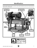
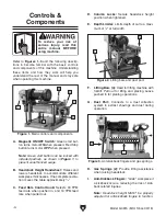
Страница 5: ... machine Become familiar with the names and locations of the controls and features shown below to better understand the instructions in this manual Magnetic ON OFF Switch Headstock Height Handwheel Gearbox Feed Rate Control Knob Column Locks 1 of 2 Lifting Bars 2 of 4 Table Headstock Height Scale Gas Spring 4 Dust Port ...

Страница 6: ...esses One complete revolu tion moves the table approximately 1 8 C Feed Rate Control Knob Selects 30 FPM feed rate when pushed in and 16 FPM feed rate when pulled out Figure 1 Main controls and components A B C D D E Figure 2 Lifting bars and dust port F G F Lifting Bars 4 Used for lifting machine with forklift Pull out for lifting and placing Leave pushed in for planing operations G Dust Port Con...

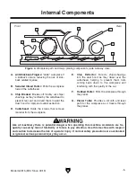
Страница 7: ...ckback occurs reducing the risk of kick back related injuries B Serrated Infeed Roller Pulls the workpiece toward the cutterhead C Chip Breaker Breaks off freshly cut chips shavings as they re lifted by the cutterhead to prevent tear out and divert them toward the dust hood for improved overall extraction D Cutterhead Holds the knives that remove material from the workpiece E Chip Deflector Direct...

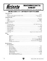
Страница 8: ... Yes Electrical Power Requirement 240V Single Phase 60 Hz Full Load Current Rating 14A Minimum Circuit Size 20A Connection Type Cord Plug Power Cord Included Yes Power Cord Length 6 ft Power Cord Gauge 12 AWG Plug Included Yes Included Plug Type 6 20 Switch Type Magnetic Switch w Overload Protection Motors Main Horsepower 3 HP Phase Single Phase Amps 14A Speed 3450 RPM Type TEFC Capacitor Start In...

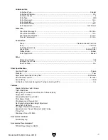
Страница 9: ...utterhead Assembly Steel Infeed Roller Serrated Steel Outfeed Roller Rubber Paint Type Finish Enamel Other Measurement Scale Inch Number of Dust Ports 1 Dust Port Size 4 in Other Specifications Country of Origin Taiwan Warranty 1 Year Approximate Assembly Setup Time 30 Minutes Serial Number Location ID Label Sound Rating 92 dB Certified by a Nationally Recognized Testing Laboratory NRTL Yes Featur...

Страница 10: ...id proof DANGEROUS ENVIRONMENTS Do not use machinery in areas that are wet cluttered or have poor lighting Operating machinery in these areas greatly increases the risk of accidents and injury MENTAL ALERTNESS REQUIRED Full mental alertness is required for safe operation of machin ery Never operate under the influence of drugs or alcohol when tired or when distracted For Your Own Safety Read Instr...

Страница 11: ... moving parts or flying debris Make sure they are properly installed undamaged and working correctly BEFORE operating machine FORCING MACHINERY Do not force machine It will do the job safer and better at the rate for which it was designed NEVER STAND ON MACHINE Serious injury may occur if machine is tipped or if the cutting tool is unintentionally contacted STABLE MACHINE Unexpected movement dur i...

Страница 12: ...stands for long stock SECURE KNIVES INSERTS Loose knives or improperly set inserts can become dangerous projectiles or cause machine damage Always verify knives inserts are secure and properly adjusted before operation KICKBACK Know how to reduce the risk of kick back and kickback related injuries Kickback occurs during the operation when the workpiece is ejected from the machine at a high rate of...

Страница 13: ...or fire may result especially if connected to an undersized circuit To reduce the risk of these hazards avoid over loading the machine during operation and make sure it is connected to a power supply circuit that meets the specified circuit requirements For your own safety and protection of property consult an electrician if you are unsure about wiring practices or electrical codes in your area No...

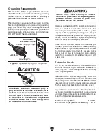
Страница 14: ...ny extension cord used with this machine must be in good condition and contain a ground wire and matching plug receptacle Additionally it must meet the following size requirements Minimum Gauge Size 12 AWG Maximum Length Shorter is Better 50 ft Figure 5 Typical 6 20 plug and receptacle Grounding Pin Current Carrying Prongs 6 20 PLUG GROUNDED 6 20 RECEPTACLE Grounding Requirements This machine MUST...

Страница 15: ...or the shipping agent You MUST have the original pack aging to file a freight claim It is also extremely helpful if you need to return your machine later Unpacking SUFFOCATION HAZARD Keep children and pets away from plastic bags or packing materials shipped with this machine This machine presents serious injury hazards to untrained users Read through this entire manu al to become familiar with the...

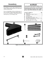
Страница 16: ...dware store NOTICE If you cannot find an item on this list care fully check around inside the machine and packaging materials Often these items get lost in packaging materials while unpack ing or they are pre installed at the factory Inventory Figure 6 Qty A Dust Hood 1 B Phillips Head Screws 10 24 x 3 8 4 C Lifting Bars 4 D Knife Setting Jig 1 E Feed Rate Control Knob 3 8 16 1 F Open End Wrenches...

Страница 17: ...es Before cleaning gather the following Disposable rags Cleaner degreaser WD 40 works well Safety glasses disposable gloves Plastic paint scraper optional Basic steps for removing rust preventative 1 Put on safety glasses 2 Coat the rust preventative with a liberal amount of cleaner degreaser then let it soak for 5 10 minutes 3 Wipe off the surfaces If your cleaner degreas er is effective the rust...

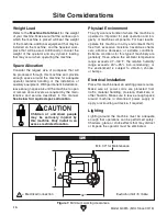
Страница 18: ...equired space allocation Physical Environment The physical environment where the machine is operated is important for safe operation and lon gevity of machine components For best results operate this machine in a dry environment that is free from excessive moisture hazardous chemi cals airborne abrasives or extreme conditions Extreme conditions for this type of machinery are generally those where ...

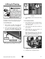
Страница 19: ...of lifting bar see Figures 8 9 Figure 9 Installing lifting bar viewed from under machine Lifting Bar x 1 Figure 8 Machine on shipping pallet and lifting bar inserted into hole in base 1 of 4 shown Lifting Bar 1 of 4 Reach Under Here Figure 10 Lifting planer with forklift 4 Set planer down on intended location Lifting Bar 1 of 4 3 Repeat Steps 1 2 with remaining three lifting bars To lift and place...

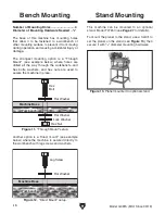
Страница 20: ...low where the machine is secured directly to the workbench with lag screws and washers The base of this machine has mounting holes that allow it to be fastened to a workbench or other mounting surface to prevent it from moving during operation and causing accidental injury or damage The strongest mounting option is a Through Mount see example below where holes are drilled all the way through the w...

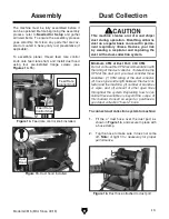
Страница 21: ...se over the dust port as shown in Figure 16 and secure in place with a hose clamp 2 Tug the hose to make sure it does not come off Note A tight fit is necessary for proper performance Minimum CFM at Dust Port 400 CFM Do not confuse this CFM recommendation with the rating of the dust collector To determine the CFM at the dust port you must consider these variables 1 CFM rating of the dust collector...

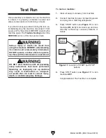
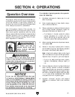
Страница 22: ...function or unexpect ed results that can lead to serious injury death or machine property damage Serious injury or death can result from using this machine BEFORE understanding its controls and related safety information DO NOT operate or allow others to operate machine until the information is understood To test run machine 1 Clear all setup tools away from machine 2 Connect machine to power by i...

Страница 23: ...ld liable for accidents caused by lack of training To complete a typical operation the operator does the following 1 Examines workpiece to make sure it is suit able for planing 2 Puts on safety glasses or face shield a respi rator and ear protection 3 Places workpiece on table with flat side down and correctly adjusts headstock height for workpiece thickness and depth of cut If workpiece is bowed ...

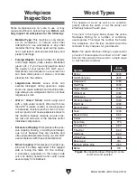
Страница 24: ...r individual components Excessive Warping Workpieces with exces sive cupping bowing or twisting are danger ous to cut because they are unstable and often unpredictable when being cut DO NOT use workpieces with these characteristics Minor Cupping Workpieces with slight cup ping can be safely supported if the cupped side is facing the table On the contrary a workpiece supported on the bowed side wil...

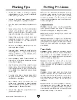
Страница 25: ...the outfeed end of the planer The best way to deal with snipe is by planing lumber longer than your intended work length and then cutting off the excess after planing is completed Cutting Problems Inspect your lumber for twisting or cupping and surface one face on a jointer if necessary before planing workpiece Scrape off all glue when planing glued up panels Dried glue can quickly dull knives DO ...

Страница 26: ...of cut Rippled Cut Problem Regularly spaced indentations across face of workpiece are caused by excessive outfeed roller pressure or excessive feed rate Solution Reduce outfeed roller pressure reduce feed rate Depth of Cut Table Movement per Handwheel Revolution One Full Revolution 4mm The depth of cut on a planer means the amount of material that is removed from the top of the workpiece as it pas...

Страница 27: ...es can result in severe cuts Take great caution whenever working with or around cutterhead knives Wear heavy leather gloves to reduce risk of severe cuts To maintain accurate and consistent plan ing results we do not recommend sharpen ing knives yourself Instead just replace dull knives or have them professionally sharpened Setting the height of the knives correctly is cru cial to the proper opera...

Страница 28: ... knife so that knife edge is directly under center pad as shown in Figure 22 Center Pad Knife Setting Jig Knife Gib Bolt Figure 22 Knife setting jig correctly positioned 7 Insert hex wrench into jack screws through access holes in cutterhead see Figure 23 Rotate jack screws to raise or lower knife until it barely touches center pad of knife setting jig with all legs of jig still firmly on cutterhe...

Страница 29: ...nchtop Planer An excellent choice if you have the floor space but not the benchtop space for this machine Figure 25 T27650 Planer Stand G2790 Universal Knife Grinder This dry type Knife Grinder with high quality cast iron construction and large knife holding capacity will sharpen up to 20 planer jointer knives makes this grinder an excellent investment Features a heavy duty 1 2 HP 110V motor knife...

Страница 30: ... get a perfect cut to an accuracy of or 002 Note When buying planer pals follow this simple guideline 15 to 20 Planers use 2 jigs Over 20 Planers use 3 jigs Figure 29 W1216A Planer Pals Standard Pair Figure 30 W1218A Rotacator Precision Planer Tool W1218A Rotacator Precision Planer Tool The Rotacator is a dial indicator on a magnetic base designed for quickly and accurately set ting the critical t...

Страница 31: ...mes with 9 ball bearing rollers and has four independently adjustable legs for any leveling requirement Adjustable in height from 263 8 to 441 8 Approximate shipping weight 62 lbs 1000 Lb Capacity D2273 Single Roller Stand D2274 5 Roller Stand These large diameter ball bearing roller stands features smooth operation for a variety of pro cessing and work support applications Each stand is equipped ...

Страница 32: ...ection H4978 T20446 H4979 Basic Eye Protection T20501 Face Shield Crown Protector 4 T20502 Face Shield Crown Protector 7 T20503 Face Shield Window T20451 Kirova Clear Safety Glasses T20452 Kirova Anti Reflective S Glasses H7194 Bifocal Safety Glasses 1 5 H7195 Bifocal Safety Glasses 2 0 H7196 Bifocal Safety Glasses 2 5 Figure 38 Assortment of basic eye protection T20451 T20452 T20502 T20503 H7194 ...

Страница 33: ...his maintenance schedule and refer to any specific instructions given in this section Note This maintenance schedule is based on average daily usage Adjust the maintenance schedule to match your usage to keep your planer running smoothly and to protect your investment Every 8 Hours of Operation Clean machine and protect unpainted cast iron Lubricate feed roller bushings Page 32 Tighten loose mount...

Страница 34: ...long life and trouble free operation of your planer NOTICE Failure to follow reasonable lubrication practices as instructed in this manual for your machine could lead to premature fail ure of components and void the warranty Feed Roller Bushings Oil Type SB1365 or ISO 68 Equivalent Oil Amount 2 3 Drops Frequency Every 8 Hours of Operation The infeed and outfeed rollers rotate inside bush ing block...

Страница 35: ...in and sprockets as viewed from underneath the base Columns Leadscrews Oil Type SB1365 or ISO 68 Equivalent Oil Amount Thin Coat Grease Type NLGI 2 Equivalent Frequency Every 40 Hours of Operation The headstock rides on the columns and is moved by the rotation of the leadscrews inside the columns see Figure 42 Apply a thin coat of ISO 68 machine oil to the outside surface of the columns and brush ...

Страница 36: ...rly Note SAE 85W 140 multi weight gear oil may also be used DO NOT mix oil types Note We recommend that you replace the gear box oil after the first 20 hours of operation This is a normal break in procedure and will help maxi mize the service life of the machine by flushing away any particles from the break in and manu facturing process Raise the headstock and place a suitable con tainer under the...

Страница 37: ...orkpiece material not suitable 3 Motor overheated 4 Belts slipping improper belt tension or oil grease on belts 5 Dull knives 6 Dust collection problem causing internal components to clog up with shavings 7 Motor wired incorrectly 8 Pulley sprocket slipping on shaft 9 Motor bearings at fault 1 Reduce depth of cut feed rate 2 Only cut wood ensure moisture is below 20 3 Allow motor to cool reset ove...

Страница 38: ...ting depth when planing hard woods 3 Slow down feed rate Page 25 4 Adjust both sides of chipbreaker to correct height Page 39 5 Replace affected knife Page 25 or have it sharpened Chipping indentation in workpiece surface inconsistent pattern 1 Chips aren t being properly expelled from cutterhead 2 Chip breaker not set correctly 1 Use a proper dust collection system Page 19 2 Correctly adjust chip...

Страница 39: ...en among the belts causing premature belt failure V belts and pulleys will be hot after opera tion Allow them to cool before handling To tension replace V belts 1 DISCONNECT MACHINE FROM POWER 2 Remove upper and lower V belt cover from left side of machine to expose belts as shown in Figure 47 Figure 47 Belt covers removed to expose V belts and pulleys V Belts Motor Pulley Cutterhead Pulley 3 Loos...

Страница 40: ...e belt ten sion adjustment bolt see Figure 48 to raise or lower motor until belts are correctly tensioned Note V belts are correctly tensioned when there is approximately 3 8 deflection when moderate pressure is applied to them midway between pulleys as illustrated in Figure 49 NOTICE DO NOT let chain fall off sprockets It can be very difficult to return chain to its proper location on sprockets w...

Страница 41: ...eded Qty Phillips Screwdriver 2 1 Hex Wrench 4 5mm 1 Ea Open End Wrench or Socket 8 10mm 1 Ea Rotacator see Page 27 1 To use a rotacator 1 DISCONNECT MACHINE FROM POWER 2 Make sure knives are set to correct height refer to Adjusting Replacing Knives on Page 25 for detailed instructions 3 Raise headstock at least 4 above table then lock it in place 4 Remove dust hood top cover belt covers and drive...

Страница 42: ...sary make further adjustments until infeed roller height from side to side is 0 040 below BDC of cutterhead knife then retighten both jam nuts 11 Keeping same 0 reference on Rotacator dial from Step 5 repeat Steps 7 10 for outfeed roller but adjust it until it is 0 020 below BDC of cutterhead knife Figure 53 Location of infeed roller height adjustment controls Roller Bushing Block Jam Nut Cap Scre...

Страница 43: ...ve table surface 5 Place wood blocks along sides of table as illustrated in Figure 55 Using Wood Blocks Tools Needed Qty Phillips Screwdriver 2 1 Hex Wrench 4 5mm 1 Ea Open End Wrench or Socket 8 10mm 1 Ea 2x4 6 Long 1 Feeler Gauge Set 1 To use wood blocks 1 Build wood blocks by cutting a straight 6 foot long 2x4 in half Note Having the wood blocks at an even height is critical to the accuracy of ...

Страница 44: ...e type of wood you are planing When adjusting the roller spring tension keep the following in mind If you are planing milled lumber with a rela tively consistent surface use less spring ten sion If you are planing rough lumber with incon sistent surfaces use greater spring tension to keep the stock moving through the planer If the workpiece consistently stops feeding during operation the roller sp...

Страница 45: ...e workpiece to easily enter the planer but reduces the risk of kickback by digging into the workpiece if it moves backward Figure 60 Anti kickback fingers Anti Kickback Fingers Check the anti kickback fingers regularly to ensure they swing freely and easily If the fingers do not swing freely and easily first clean them with a wood resin solvent then inspect them for dam age If any of the fingers a...

Страница 46: ...nt at the time of printing but may not match your machine If you find this to be the case use the wiring diagram inside the motor junction box CAPACITORS INVERTERS Some capacitors and power inverters store an electrical charge for up to 10 minutes after being disconnected from the power source To reduce the risk of being shocked wait at least this long before working on capacitors EXPERIENCING DIF...

Страница 47: ...Motor Start Capacitor CD60 600MFD 125VAC A RESET 96 98 T1 2 T3 6 8 T2 4 L1 1 L3 5 7 L2 3 95 12 15 18 SET 14A GND 1 2 3 4 5 6 Relay RA 20 Contactor SDE MA 15 220V 240V Magnetic Switch Hot Hot Ground 6 20 Plug 220 VAC G Figure 61 Magnetic switch with cover removed Figure 62 Motor wiring ...

Страница 48: ...62 62 63 63 63 64 64 65 66 67 67 98 101 102 22 22 22 105 104 106 107 109 109 110 152 111 112 115 120 121 122 123 124 125 140 140 141 141 142 141A 143 144 145 146 147 148 149 41 1 41 2 41 3 78 113 74 73 78 78 81 75 79 78 80 69 92 91 90 97 96 95 89 78 82 84 22 56 76 72 77 88 71 70 87 94 85 99 48 86 93 103 126 153 40 100 42 42 Main SECTION 9 PARTS We do our best to stock replacement parts when possib...

Страница 49: ...15017 BALL BEARING 6000 2RS 72 P0815072 CAP SCREW 1 4 20 X 1 1 4 18 P0815018 LOCK WASHER 10MM 73 P0815073 GEAR 46T 19 P0815019 FLANGE SCREW 1 4 20 X 3 8 74 P0815074 GEARED SHAFT 18T 20 P0815020 ROLL PIN 5 X 15 75 P0815075 KEY 5 X 5 X 10 21 P0815021 HEX NUT 3 8 16 76 P0815076 GEARBOX COVER 22 P0815022 FLAT WASHER 1 4 77 P0815077 GEARBOX COVER PIN 23 P0815023 HANDWHEEL TYPE 3 8 5 D X 3 8B K X 3 8 16...

Страница 50: ...15110 SET SCREW 1 4 20 X 3 16 143 P0815143 HEX WRENCH 6MM 111 P0815111 CUTTERHEAD PULLEY 144 P0815144 HEX WRENCH 2 5MM 112 P0815112 BELT HOUSING 145 P0815145 HEX WRENCH 4MM 113 P0815113 KEY 5 X 5 X 12 146 P0815146 HEX WRENCH 3MM 115 P0815115 SHAFT 147 P0815147 WRENCH 8 X 10MM OPEN ENDS 116 P0815116 LOCK WASHER 10 148 P0815148 WRENCH 12 X 14MM OPEN ENDS 117 P0815117 HEX NUT 10 24 149 P0815149 T HAN...

Страница 51: ...ALL BEARING 6302ZZ 208 P0815208 PHLP HD SCR 10 24 X 3 8 225 P0815225 INT RETAINING RING 42MM 209 P0815209 LEADSCREW NUT 226 P0815226 ELEVATION SPROCKET 10T 210V2 P0815210V2 ELEVATION LEADSCREW V2 09 18 227V2 P0815227V2 DEPTH SCALE V2 09 18 211 P0815211 CAP SCREW 1 4 20 X 1 2 229V2 P0815229V2 DRIVE COLUMN V2 09 18 212V2 P0815212V2 COLUMN V2 09 18 232 P0815232 LEADSCREW BUSHING 213 P0815213 COLUMN B...

Страница 52: ...er before doing any service on machine 4 Only plug power cord into a grounded outlet 5 Do not wear loose clothing gloves jewelry or items that can get entangled Tie back long hair and roll up sleeves 6 Ensure machine is correctly set up before starting 7 Never cut deeper than 1 8 on a single pass 8 Never plane material smaller than 8 long 3 4 wide or 1 4 thick 9 Do not allow hands or clothing to g...

Страница 53: ... metalworker ____ 0 2 Years ____ 2 8 Years ____ 8 20 Years ____20 Years 6 How many of your machines or tools are Grizzly ____ 0 2 ____ 3 5 ____ 6 9 ____10 7 Do you think your machine represents a good value _____Yes _____No 8 Would you recommend Grizzly Industrial to a friend _____Yes _____No 9 Would you allow us to use your name as a reference for Grizzly customers in your area Note We never use ...

Страница 54: ...D LINE FOLD ALONG DOTTED LINE GRIZZLY INDUSTRIAL INC P O BOX 2069 BELLINGHAM WA 98227 2069 Place Stamp Here Name_______________________________ Street_______________________________ City______________State______Zip______ Send a Grizzly Catalog to a friend ...

Страница 55: ... shall be tried in the State of Washington County of Whatcom We shall in no event be liable for death injuries to persons or property or for incidental contingent special or consequential damages arising from the use of our products To take advantage of this warranty contact us by mail or phone and give us all the details We will then issue you a Return Number which must be clearly posted on the o...

Страница 56: ......
Отзывы: