Grizzly G0803Z Скачать руководство пользователя страница 55

Model G0803Z (Mfd. Since 12/18)

-53-

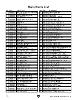
Main Parts List (Cont.)

REF PART #

DESCRIPTION

REF PART #

DESCRIPTION

105

P0803Z105

CAP SCREW M5-.8 X 12

138

P0803Z138

COMPRESSION SPRING 2.5 X 14 X 64

106

P0803Z106

SHOULDER SCREW M5-.8 X 10, 6 X 6

139

P0803Z139

CARRIAGE BOLT M8-1.25 X 80

107

P0803Z107

BALL BEARING 606-2RS

140

P0803Z140

WHEEL ADJUSTMENT BRACKET

108

P0803Z108

CAP SCREW M5-.8 X 16

141

P0803Z141

QUICK-RELEASE PIVOT SHAFT 8 X 90

109

P0803Z109

BLADE GUIDE ROD (LOWER)

142

P0803Z142

EXT RETAINING RING 8MM PUSH-ON

110

P0803Z110

BLADE GUIDE (LOWER)

143

P0803Z143

CAP SCREW M5-.8 X 8

111

P0803Z111

BLADE GUIDE SLIDING COVER (UPPER)

144

P0803Z144

LOCK WASHER 10MM

112

P0803Z112

BLADE GUIDE COVER (UPPER)

145

P0803Z145

WHEEL MOUNT PLATE

113

P0803Z113

DOWEL PIN 3 X 15 W/COMP SPRING

146

P0803Z146

WHEEL SHAFT (UPPER)

114

P0803Z114

BLADE GUIDE DOOR (UPPER)

147

P0803Z147

INT RETAINING RING 26MM

115

P0803Z115

BLADE GUIDE ROD (UPPER)

148

P0803Z148

WHEEL (UPPER)

116

P0803Z116

PHLP HD SCR M4-.7 X 10

149

P0803Z149

BANDSAW TIRE 9-5/16"

117

P0803Z117

BLADE GUIDE (UPPER)

150

P0803Z150

BLADE 62" X 3/8" X 0.025" 10-TPI RAKER

118

P0803Z118

FENCE END CAP

151

P0803Z151

WHEEL COVER (UPPER)

119

P0803Z119

FENCE

152

P0803Z152

BLADE VIEW WINDOW, PLASTIC

120

P0803Z120

CAP SCREW M6-1 X 8

153

P0803Z153

GRIZZLY NAMEPLATE-MINI

121

P0803Z121

FENCE HOLE PLUG

154

P0803Z154

PHLP HD SCR M3-.5 X 6

122

P0803Z122

FENCE SPACER PLATE

155

P0803Z155

LASER SIGHT BOX

123

P0803Z123

FENCE BASE CLIP

156

P0803Z156

LASER SIGHT SWITCH

124

P0803Z124

FENCE BASE

157

P0803Z157

LASER SIGHT

125

P0803Z125

LOCK NUT M6-1

158

P0803Z158

LASER SIGHT BOX COVER

126

P0803Z126

PHLP HD SCR M4-.7 X 6

159

P0803Z159

WHEEL COVER (LOWER)

127

P0803Z127

FENCE POINTER

160

P0803Z160

STANDOFF-SE-ROUND F M5-.8, 17

128

P0803Z128

SET SCREW M6-1 X 8

161

P0803Z161

HEX WRENCH 2MM

129

P0803Z129

CAP SCREW M6-1 X 30

162

P0803Z162

HEX WRENCH 4MM

130

P0803Z130

FENCE HANDLE LOCKING CAM

163

P0803Z163

BEARING SHAFT

131

P0803Z131

FIXED HANDLE 32 X 76, M6-1 X 12

164

P0803Z164

BALL BEARING 696-2RS

135

P0803Z135

SPRING PLATE

165

P0803Z165

EXT RETAINING RING 5MM

136

P0803Z136

PHLP HD SCR M5-.8 X 6

166

P0803Z166

SET SCREW M5-.8 X 5

137

P0803Z137

KNOB M8-1.25, D50, 5-LOBE

167

P0803Z167

HEX NUT M3-.5

Содержание G0803Z

Страница 1: ...or models manufactured since 12 18 COPYRIGHT JANUARY 2019 BY GRIZZLY INDUSTRIAL INC WARNING NO PORTION OF THIS MANUAL MAY BE REPRODUCED IN ANY SHAPE OR FORM WITHOUT THE WRITTEN APPROVAL OF GRIZZLY IND...

Страница 2: ...g grinding tool integrity and the usage of personal protective equipment The manufacturer will not be held liable for injury or property damage from negligence improper training machine modifications...

Страница 3: ...5 ACCESSORIES 36 SECTION 6 MAINTENANCE 39 Schedule 39 Cleaning Lubricating 39 SECTION 7 SERVICE 40 Troubleshooting 40 Checking Adjusting Belt Tension 43 Replacing Belt 44 Wheel Alignment 45 Blade Lea...

Страница 4: ...ade every effort to be exact with the instruc tions specifications drawings and photographs in this manual Sometimes we make mistakes but our policy of continuous improvement also means that sometimes...

Страница 5: ...until blade has stopped c Maintain proper adjustment of blade tension blade guides and thrust bearings d Adjust upper blade guide to just clear workpiece e Hold workpiece firmly against table Storage...

Страница 6: ...cuts Adjusts 60 left or right C Miter Gauge Lock Knob Secures angle position of miter gauge D Fence Lock Handle Secures fence position D Basic Controls Components Figure 1 Basic Controls Components A...

Страница 7: ...e as viewed from rear of machine to quickly release blade tension Move clockwise to re tension blade J Tracking Knob Rotate to adjust blade track ing refer to Page 17 for more information K Trunnion w...

Страница 8: ...18 x 14 in Must Ship Upright No Electrical Power Requirement 120V Single Phase 60 Hz Full Load Current Rating 2 8A Minimum Circuit Size 15A Connection Type Cord Plug Power Cord Included Yes Power Cor...

Страница 9: ...num Base Stand Pre Formed Steel Frame Body Pre Formed Steel Wheels Balanced Aluminum Tire Rubber Wheel Cover Steel Paint Type Finish Urethane Other Related Information Wheel Diameter 9 5 16 in Wheel W...

Страница 10: ...d proof DANGEROUS ENVIRONMENTS Do not use machinery in areas that are wet cluttered or have poor lighting Operating machinery in these areas greatly increases the risk of accidents and injury MENTAL A...

Страница 11: ...moving parts or flying debris Make sure they are properly installed undamaged and working correctly BEFORE operating machine FORCING MACHINERY Do not force machine It will do the job safer and better...

Страница 12: ...oss of control If necessary use a jig or other work holding device WORKPIECE MATERIAL This machine is intended for cutting natural and man made wood products and laminate covered wood products This ma...

Страница 13: ...rsized circuit To reduce the risk of these hazards avoid over loading the machine during operation and make sure it is connected to a power supply circuit that meets the specified circuit requirements...

Страница 14: ...ord size gets longer and the gauge size gets smaller higher gauge numbers indicate smaller sizes Any extension cord used with this machine must be in good condition and contain a ground wire and match...

Страница 15: ...HAZARD Keep children and pets away from plastic bags or packing materials shipped with this machine The following is a list of items shipped with your machine Before beginning setup lay these items o...

Страница 16: ...ow is the minimum amount of space needed for the machine Placement Location Bench Mounting Figure 10 Direct Mount setup Machine Base Workbench Lag Screw Flat Washer Another option is a direct mount se...

Страница 17: ...e guide post all the way up 4 Remove wing bolt lock washer flat washer and D nut from table assembly Make note of how fasteners secure to fence assembly for re installation later 5 Using gap in table...

Страница 18: ...ion Figure 15 Table tilt controls re installed Table Tilt Scale Lock Lever Set Indicator to 0 When Table is Perpendicular to Blade Figure 16 Fence installed on fence rail Fence Lock Lever Fence on Fen...

Страница 19: ...is important for maintaining bandsaw adjustments achiev ing correct blade tension and cutting accurate ly Improper tracking reduces cutting accuracy causes excess vibrations and places stress on the...

Страница 20: ...d lower blade guides away from blade and raise upper guides all the way up refer to Adjusting Blade Guide Bearings on Page 23 for detailed instruc tions Note When adjusting the blade tracking for the...

Страница 21: ...of 2 dust hose attached to dust port To connect a dust collection hose 1 Fit dust hose over 2 dust port as shown in Figure 21 and secure it in place with a hose clamp Dust Collection Dust Collectio Re...

Страница 22: ...its controls and related safety information DO NOT operate or allow others to operate machine until the information is understood To test run machine 1 Clear all setup tools away from machine 2 Connec...

Страница 23: ...will help you properly tension the blade Experience and personal pref erence will help you decide which method you prefer Tensioning Blade Note Tensioning the blade before the Test Run was an approxim...

Страница 24: ...justing Blade Support Bearings and Adjusting Blade Guide Bearings on Pages This Page 23 The Deflection Method Adjusting Blade Support Bearings The support bearings are positioned behind the blade near...

Страница 25: ...de to side support from just behind the gullets to the back of the blade to help keep the blade straight while cutting There are blade guide bearings on the upper and lower blade guide assemblies Both...

Страница 26: ...acting guide bearings during operation refer to Page 22 for details Tooth Set Wider Than Blade Thickness BladeThickness Figure 27 Illustration of blade tooth set 3 Loosen both guide bearing adjustment...

Страница 27: ...ween straightedge and miter slot see Figure 29 Distance should be same at front and back of table If distance is same at front and back of table no adjustment is necessary If distance is not same at f...

Страница 28: ...gned with blade see Adjusting Miter Slot Parallelism on Page 25 for instructions 3 Install fence on right side of blade aligned with edge of miter slot then lock it in place If fence is parallel with...

Страница 29: ...fingers away from the blade and uses a push stick to feed narrow workpieces 10 Turns off laser sight if necessary and stops the bandsaw The purpose of this overview is to provide the nov ice machine o...

Страница 30: ...y The switch can be disabled by removing the key as shown below Disabling the switch in this man ner can prevent unauthorized operation of the machine which is important if it is not kept inside an ac...

Страница 31: ...eces that do not have large loose knots or plan ahead to avoid cutting through them Wet or Green Stock Cutting wood with a moisture content over 20 causes unneces sary wear on the blades increases the...

Страница 32: ...cutting operation Blade Length Measured by the circumference blade lengths are usually unique to the brand of your bandsaw and the distance between wheels Blades will vary slightly even in the same le...

Страница 33: ...coarse pitch will cut rougher but faster As a general rule choose blades that will have at least three teeth in the material at all times Use fine pitched blades on harder woods and coarse pitched bla...

Страница 34: ...D Bandsaw blades are sharp and difficult to handle Wear heavy leather gloves while handling to reduce the risk of being cut Figure 37 Example of removing blade 8 Position new blade so teeth are facing...

Страница 35: ...tick when ripping narrow pieces Failure to follow these warnings may result in amputation or laceration injuries Crosscutting is the process of cutting across the grain of wood For plywood and other p...

Страница 36: ...PI because they offer larg er gullet capacities for clearing sawdust which reduces heat buildup and strain on the motor Cutting Curves When cutting curves simultaneously feed and turn the stock carefu...

Страница 37: ...er that will not interfere with cutting Hot glue on the edges works well as do brad nails through the waste portion Be careful not to cut into the brads or you may break the blade 3 Lay out the shape...

Страница 38: ...h Performance HP and Raker RK blades are specifically designed for detail work in 1 and smaller kiln dried wood when a very clean finish is required They are also effec tive in plywood and other woods...

Страница 39: ...Grounding Kit We ve hand picked a selection of dust collection components commonly needed to connect your new machine to basic dust collection Figure 44 Dust collection accessories W1315 W1317 W1007...

Страница 40: ...ure stability and reduce machine vibration Butcher block finish table top measures 1 x 13 x 23 and is 30 1 2 from the floor Bottom measures 21 x 32 700 lb Capacity Figure 48 D2056 Tool Table T10456 He...

Страница 41: ...wear Remove blade and thoroughly clean all built up sawdust from the rubber tires on the wheels Clean vacuum dust buildup from inside cabi net and off motor Schedule To reduce risk of shock or acciden...

Страница 42: ...g on wheels 7 Belt slipping 8 Motor overheated 9 Run capacitor at fault 10 Pulley sprocket slipping on shaft 1 Only cut wood ensure moisture is below 20 2 Decrease feed rate cutting speed 3 Sharpen re...

Страница 43: ...Adjust blade guide bracket 4 Adjust blade guides as close to workpiece as possible Pages 22 23 5 Check blade installation make sure teeth face front of machine and point down in table throat Re instal...

Страница 44: ...ounting bolts or tilt lock lever 8 Align table and fence with blade Pages 25 26 9 Adjust blade guide bearings and support bearing for correct blade support Pages 22 23 10 Replace blade Page 32 11 Use...

Страница 45: ...om back of machine until you feel moderate tension then re tighten both cap screws 4 Check belt tension If necessary repeat Steps 2 3 until there is approximately 1 4 deflection in the belt 5 Close wh...

Страница 46: ...r and remove belt from motor pulley To ensure optimum power transmission from the motor to the blade the belt must be in good condi tion and be properly tensioned Replace the belt if it shows signs of...

Страница 47: ...eels are coplanar Figure 55 Wheel alignment illustration or Wheels parallel and aligned No adjust ment needed Wheels parallel but upper or lower wheel is not coplanar with the other wheel Move the upp...

Страница 48: ...gure 56 The dis tance measured with the ruler is the distance this wheel must be shimmed 4 Remove blade 5 Remove wheel to be shimmed Place as many shims as necessary to correct gap measured in Step 3...

Страница 49: ...with a pencil or marker to indicate measuring locations see Figure 58 Note Marking the wheels ensures more accurate results in case there are irregulari ties in the wheels 5 Loosen hex nuts on rear le...

Страница 50: ...o fence adjustment cap screws skew fence so that it is parallel with scrap piece then re tighten cap screws 5 Make a few cuts using fence If blade lead is still present repeat Steps 1 4 until blade an...

Страница 51: ...t at the time of printing but may not match your machine If you find this to be the case use the wiring diagram inside the motor junction box CAPACITORS INVERTERS Some capacitors and power inverters s...

Страница 52: ...dy Bandsaw Column 5 15 Plug 120VAC Ground Hot Neutral Ground Chip Blower Motor Nanjing 12V 3 5W LED Light Nanjing 12V 1W ON OFF Switch KEDU HY18 250V 12A Transformer Feng 009F 120V Wiring Diagram Figu...

Страница 53: ...5 141 142 143 144 14 140 139 138 137 49 112 111 113 114 18 108 107 106 105 18 115 116 100 99 94 95 96 98 83 94 82 2 82 83 97 30 84 88 87 66 89 11 90 91 92 93 85 11 86 75 73 66 78 72 70 74 71 55 11 85...

Страница 54: ...8 X 6 28 P0803Z028 COMPRESSION SPRING 0 8 X 10 X 25 77 P0803Z077 QUICK RELEASE ECCENTRIC SHAFT 29 P0803Z029 GEARED KNOB 8 X 39 D46 12T 78 P0803Z078 WAVY WASHER 16 X 21 X 0 3MM 30 P0803Z030 PHLP HD SC...

Страница 55: ...5 16 117 P0803Z117 BLADE GUIDE UPPER 150 P0803Z150 BLADE 62 X 3 8 X 0 025 10 TPI RAKER 118 P0803Z118 FENCE END CAP 151 P0803Z151 WHEEL COVER UPPER 119 P0803Z119 FENCE 152 P0803Z152 BLADE VIEW WINDOW P...

Страница 56: ...touch moving blade keep hands out of blade path 3 Always wear approved eye protection and respirator 4 Only plug power cord into a grounded outlet 5 Only remove jammed cutoff pieces when blade is stop...

Страница 57: ...metalworker ____ 0 2 Years ____ 2 8 Years ____ 8 20 Years ____20 Years 6 How many of your machines or tools are Grizzly ____ 0 2 ____ 3 5 ____ 6 9 ____10 7 Do you think your machine represents a good...

Страница 58: ...LINE FOLD ALONG DOTTED LINE GRIZZLY INDUSTRIAL INC P O BOX 2069 BELLINGHAM WA 98227 2069 Place Stamp Here Name_______________________________ Street_______________________________ City______________S...

Страница 59: ...tried in the State of Washington County of Whatcom We shall in no event be liable for death injuries to persons or property or for incidental contingent special or consequential damages arising from...

Страница 60: ......

Отзывы: