


-24-
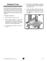
Model G0803Z (Mfd. Since 12/18)
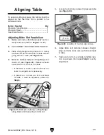
Blade
Guide
Bearing
(1 of 2)
Blade
Gullets
Approximately
0.016"
Figure 26. Blade guide bearing positioned just
behind blade gullets.
Note: With wider blades, it may not be possi-
ble to bring the guide bearings just behind the
blade gullets. Position them as far forward as
possible without allowing the guide bearing
housing to touch the back of the blade.
Blade teeth are angled out slightly, protrud-
ing wider than the blade thickness; this is
known as blade "tooth set" (see Figure 27).
If teeth contact guide bearings during oper-
ation, damage may occur. Therefore, the
support bearing must be set to prevent
teeth from contacting guide bearings during
operation (refer to Page 22 for details).
“Tooth Set”
Wider Than
Blade Thickness
BladeThickness
Figure 27. Illustration of blade "tooth set".
3. Loosen both guide bearing adjustment cap
screws (see
Figure 25 on Page 23), then
position guide bearings so they evenly and
lightly touch sides of blade (see illustration
in
Figure 28) without deflecting it one way or
the other.
Note: When the blade guide bearings are
properly adjusted against the blade, they
should lightly rotate as the blade moves.
Figure 28. Blade guide bearings evenly and
lightly touching the sides of the blade.
4. Re-tighten cap screws to secure settings.
Re-check the setting after tightening.
Whenever changing blade or adjusting
blade tension or tracking, the support and
guide bearings must be re-adjusted before
resuming operation to ensure proper blade
support.
Содержание G0803Z
Страница 60: ......


