


-50-
Model G0720R (Mfg. Since 11/10)
401
402
403
404
405
406
407
408
409
401
401
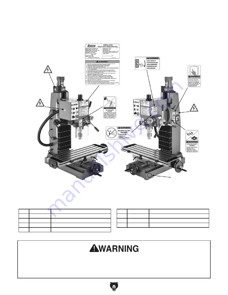
Label Placement
Safety labels warn about machine hazards and ways to prevent injury. The owner of this machine
MUST maintain the original location and readability of the labels on the machine. If any label is
removed or becomes unreadable, REPLACE that label before using the machine again. Contact
Grizzly at (800) 523-4777 or www.grizzly.com to order new labels.
REF PART #
DESCRIPTION
REF PART #
DESCRIPTION
401
P0720R401
ELECTRICITY LABEL
406
P0720R406
EYE/LUNG HAZARD LABEL
402
P0720R402
MACHINE ID LABEL
407
P0720R407
ROTATING CUTTER WARNING LABEL
403
P0720R403
MACHINE WARNING LABEL
408
P0720R408
ENTANGLEMENT HAZARD LABEL
404
P0720R404
DISCONNECT POWER WARNING
409
P0720R409
GRIZZLY GREEN TOUCH-UP PAINT
405
P0720R405
READ MANUAL LABEL
Содержание G0720R
Страница 56: ......


