


Model g0661/g0713 (Mfg. since 1/10)
-27-
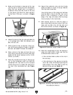
18. turn the lock knob that secures the table
insert so it is parallel to the inner slot, as
shown in
Figure 28, then remove the insert
and set it aside.
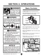
Figure 30. Example of securing blade.
Figure 28. Example of insert lock knob
unlocked.
lock Knob
19.
raise the arbor all the way up and set the
arbor angle to 0°.
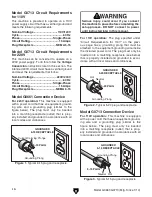
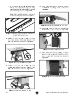
20. unthread the lock knob on the riving knife/
blade guard mounting block (see
Figure 29)
several turns. push the riving knife away
from the knob, then lift the riving knife up to
remove it.
Figure 29. Example of riving knife installed.
lock
Knob
riving Knife
Mounting
Block
the riving knife is installed for shipping pur-
poses. although it is possible to use the riving
knife for through cutting operations, the blade
guard assembly offers far more injury protec-
tion and risk reduction than the riving knife.
therefore,
we strongly recommend that
you use the blade guard instead of the riving
knife for through cuts.
Note:
The two pins in the mounting block fit
into matching slots on the riving knife, keep-
ing it secured.
21. remove the arbor nut and arbor flange from
the arbor, slide on the included 10" saw
blade, making sure the teeth face the front
of the saw, then install the arbor flange and
arbor nut onto the blade. (refer to
page 36
for detailed blade installation instructions.)
22. put on a pair of heavy leather gloves and use
the included arbor wrenches to tighten the
arbor nut, as shown in
Figure 30, then lower
the blade all the way down.
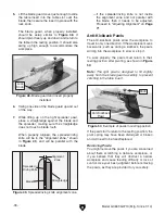
23. install the fence lock handle, as shown in
Figure 31.
24. Mount the fence on the front rail to the right of
the blade.
25. slide the miter gauge into the t-slot on the
left side of the blade.
26. Follow instructions in Dust Collection, power
Connection, and Test Run, then proceed
to
Final Setup to complete the remaining
assembly steps.
Figure 31. Fence lock handle installed on fence.
handle


