


-16-
G0641 Double Miter Saw
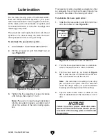
Figure 13.
Dust hose attached to dust port.
Dust Collection
To connect a dust collection hose:
1.
Fit a 4" dust hose over the dust port, as
shown in
Figure 13
, and secure it in place
with a hose clamp.
2.
Tug the hose to make sure it does not come
off.
Note:
A tight fit is necessary for proper per-
formance.
DO NOT operate the Model G0641 without an
adequate dust collection system. This saw
creates substantial amounts of wood dust
while operating. Failure to use a dust collec-
tion system can result in short and long-term
respiratory illness.
Recommended CFM at Dust Port: 400 CFM
Do not confuse this CFM recommendation with
the rating of the dust collector. To determine
the CFM at the dust port, you must consider
these variables: (1) CFM rating of the dust col-
lector, (2) hose type and length between the
dust collector and the machine, (3) number
of branches or wyes, and (4) amount of other
open lines throughout the system. Explaining
how to calculate these variables is beyond the
scope of this manual. Consult an expert or pur-
chase a good dust collection "how-to" book.
Содержание G0641
Страница 2: ......
Страница 5: ...G0641 Double Miter Saw 3 Machine Data Sheet machine data sheet...
Страница 7: ...G0641 Double Miter Saw 5 Safety Instructions for Machinery...
Страница 8: ...6 G0641 Double Miter Saw...
Страница 41: ...G0641 Double Miter Saw 39 SECTION 8 PARTS Cabinet Breakdown...
Страница 43: ...G0641 Double Miter Saw 41 Drive System Breakdown table inserts...
Страница 47: ...G0641 Double Miter Saw 45 Electrical Lubrication Systems Breakdown...
Страница 49: ...G0641 Double Miter Saw 47 Pneumatic System Breakdown pneumatic system breakdown...
Страница 52: ...50 G0641 Double Miter Saw...
Страница 53: ......
Страница 54: ......
Страница 55: ...WARRANTY AND RETURNS WARRANTY AND RETURNS...
Страница 56: ......