Grizzly G0641 Скачать руководство пользователя страница 10

-8-

G0641 Double Miter Saw

Full Load Amperage Draw

Total Motor Draw .................................. 20 Amps

Power Supply Circuit Requirements

You MUST connect your machine to a grounded 
circuit that is rated for the amperage given below. 
Never replace a circuit breaker on an existing cir-
cuit with one of higher amperage without consult-
ing  a  qualified  electrician  to  ensure  compliance 
with wiring codes. 

If you are unsure about the 

wiring codes in your area or you plan to con-

nect your machine to a shared circuit, consult 

a qualified electrician.

Minimum Circuit Size .............................30 Amps

SECTION 2: CIRCUIT REQUIREMENTS

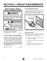
Power Connection Device

The type of plug required to connect your machine 
to power depends on the type of service you cur-
rently have or plan to install. We recommend using 
the plug and receptacle shown in 

Figure 2

.

Serious  personal  injury  could  occur  if  you 

connect the machine to power before com-

pleting the setup process. DO NOT connect 

the  machine  to  the  power  until  instructed 

later in this manual.

Electrocution or fire could 

result  if  machine  is  not 

grounded and installed in 

compliance with electrical 

codes.  Compliance  MUST 

be  verified  by  a  qualified 

electrician!

Extension Cords

Using extension cords may reduce the life of the 
motor.  Instead,  place  the  machine  near  a  power 
source. If you must use an extension cord:

• 

Use  at  least  a  12  gauge  cord  that  does  not 
exceed 50 feet in length.

• 

The extension cord must have a ground wire 
and plug pin.

• 

A qualified electrician MUST size cords over 
50 feet long to prevent motor damage.

Figure 2. 

NEMA L6-30 plug and receptacle.

220V Single-Phase

Содержание G0641

Страница 1: ...R SAW OWNER S MANUAL COPYRIGHT JANUARY 2008 BY GRIZZLY INDUSTRIAL INC WARNING NO PORTION OF THIS MANUAL MAY BE REPRODUCED IN ANY SHAPE OR FORM WITHOUT THE WRITTEN APPROVAL OF GRIZZLY INDUSTRIAL INC TS...

Страница 2: ......

Страница 3: ...ollection 16 Test Run 17 SECTION 4 OPERATIONS 18 Operation Safety 18 Operational Overview 18 Hold downs 19 Lowering Speeds 20 Fence Stop 21 Replacing Blades 22 SECTION 5 ACCESSORIES 23 SECTION 6 MAINT...

Страница 4: ...the part of Grizzly For your convenience we always keep current Grizzly manuals available on our website at www grizzly com Any updates to your machine will be reflected in these manuals as soon as t...

Страница 5: ...G0641 Double Miter Saw 3 Machine Data Sheet machine data sheet...

Страница 6: ...Left Extension Wing w Scale B Transparent Guard C Front Guard D Oil Reservoir E Safety Hood F ON OFF Magnetic Switch Identification A B C D E F G H I J K G Right Extension Wing H Pneumatic Connection...

Страница 7: ...G0641 Double Miter Saw 5 Safety Instructions for Machinery...

Страница 8: ...6 G0641 Double Miter Saw...

Страница 9: ...ury make sure that proper repairs are completed before re connecting the machine to power 13 EXPERIENCING DIFFICULTIES If at any time you are experiencing difficulties performing the intended operatio...

Страница 10: ...service you cur rently have or plan to install We recommend using the plug and receptacle shown in Figure 2 Serious personal injury could occur if you connect the machine to power before com pleting...

Страница 11: ...needed 1 4 Hose Clamp 1 Air Compressor 1 Air Hose length as needed 1 Forklift rated for 1500 lbs 1 Items Needed for Setup Your machine was carefully packaged for safe transportation Remove the packag...

Страница 12: ...g 1 D Support Legs w Adjustable Floor Mounts 2 E Hex Wrench Set 1 5 10mm 1 F Combo Wrenches 11 13mm 1 12 14mm 1 17 19mm 1 22 24mm 1 23 26mm 1 G Hardware Bag not shown Special Hex Bolts 5 8 11 x 23 8 l...

Страница 13: ...protective coating with a solvent cleaner or citrus based degreaser such as Grizzly s G7895 Citrus Degreaser To clean thoroughly some parts must be removed For optimum performance from your machine c...

Страница 14: ...hen tighten the jam nuts down to the mounting flange to lock the lifting bolts in place 5 Spread the forklift forks as far as possible and insert them under the machine 6 With assistance to steady the...

Страница 15: ...ods for mounting your machine and choose the best that fits your specific application Mounting to Shop Floor NOTICE Anchor studs are stronger and more perma nent alternatives to lag anchors and bolts...

Страница 16: ...and mount them to the flanges on both sides of the saw table see Figure 10 with the M8 1 25 x 20 hex bolts and flat washers Note The extension wing with the scale is mounted on the left side of the ma...

Страница 17: ...t Valve 2 Lift up on the air pressure knob see Figure 11 and turn it to adjust the air pressure dial to 70 PSI then push the knob down to lock the setting 3 Open the pneumatic access door on the right...

Страница 18: ...wood dust while operating Failure to use a dust collec tion system can result in short and long term respiratory illness Recommended CFM at Dust Port 400 CFM Do not confuse this CFM recommendation wit...

Страница 19: ...both regu lators then turn the machine ON 6 Listen to and watch for abnormal noises or actions The machine should run smoothly with little or no vibration or rubbing noises Strange or unusual noises s...

Страница 20: ...45 cuts in a high production shop This is accomplished by using two opposing 12 saw blades and motors with the blades rotat ing down through the workpiece in guillotine type movement The stock is posi...

Страница 21: ...d down jam nuts 6 Position the hold downs horizontally along the mounting bars over the flatest part of the workpiece so that they grip and secure the workpiece against the fence 7 Re tighten the jam...

Страница 22: ...g and raising speeds of the blades to produce cuts that are without tear out too fast and without burning too slow Note Turning the speed knob in clockwise decreases the speed and turning out coun ter...

Страница 23: ...n lower and secure the front guard Fence Stop Use the fence stop for repetitive cuts of the same dimensions Loosen the lock lever slide the stop along the fence rail to the correct setting then re tig...

Страница 24: ...lade arm assemblies and motors 3 Use a 14mm wrench on the inner arbor nut see Figure 35 and a 19mm wrench on the arbor bolt to remove the arbor bolt arbor flange and saw blade Note The left saw blade...

Страница 25: ...intain maximum stability for the best cut Each blade is hand straightened to a runout of 0 001 0 002 for maximum cut quality The tooth style 4 points and a flat maximizes steady clean cuts with no bot...

Страница 26: ...ANSI Z87 1 2003 specifica tions Buy extras for visitors or employees You can t be too careful with shop safety Figure 28 Our most popular eye protection T20448 H0736 T20452 T20501 T20456 Oldham Pro Se...

Страница 27: ...aming these clamps are designed to con sistently hold and secure stock at a 90 angle Clamps uneven thicknesses Figure 32 Bessey Angle Clamp H8888 Kreg Framing Table Assembling frames in a production s...

Страница 28: ...safe condition Schedule Vacuum excess wood chips and sawdust and wipe off the remaining dust with a dry cloth If any resin has built up use a resin dissolving cleaner like OxiSolv spray to remove it s...

Страница 29: ...face of the rams during opera tion 2 Turn the flow adjustment screw counterclock wise to increase the flow rate of lubricant 3 Flip the valve lever up as shown in Figure 35 to start the flow of lubric...

Страница 30: ...e fittings 5 Re install the inner blade guard and blades then lower and secure the front guard before continuing operation 3 Raise the front guard up and remove the inner blade guard and blades to acc...

Страница 31: ...0 Blade arbor bolt flange and nut left side shown Inner Arbor Nut Arbor Bolt Flange 3 Use a 14mm wrench on the inner arbor nut see Figure 40 and a 19mm wrench on the arbor bolt to remove the arbor bol...

Страница 32: ...lts evenly until there is approxi mately 3 4 deflection of the V belts between the pulleys when moderate pressure is applied see Figure 44 7 Use a 10mm wrench to loosen the tensioning jam nuts and bol...

Страница 33: ...ty 8 Ensure power supply is switched on ensure power supply has the correct voltage 9 Check for broken wires or disconnected corroded connections and repair replace as necessary 10 Replace faulty ON O...

Страница 34: ...g 1 Applying too much pressure to workpiece 2 V belts loose or worn 1 Reduce blade lowering speed Page 20 2 Re tension replace V belts Page 29 Excessive vibration 1 Loose arbor nut 2 Blade out of bala...

Страница 35: ...o trace air flow check for pinched clogged air line and air flow at connections clean repair replace as need ed 6 Test clean replace 7 Test clean replace Hold downs not securing workpiece when cutting...

Страница 36: ...arm assemblies 1 DISCONNECT SAW FROM POWER 2 Raise the front guard up and remove the inner blade guard to access the pivot arm assemblies and motors see Figure 45 Figure 45 Guards removed to access pi...

Страница 37: ...guard in the down position 11 Make a cut to confirm that the blades cut a 45 angle Repeat the steps above if neces sary Pneumatic Limit Switch The pneumatic limit switch see Figure 48 is activated wh...

Страница 38: ...0641 Double Miter Saw Electrical Wiring Diagram Figure 50 Junction block inside pneumatic cabinet Figure 49 ON OFF magnetic switch wiring Figure 51 Safety switch wiring electrical wiring To Motors Pag...

Страница 39: ...iter Saw 37 Motor Wiring Diagram motor wiring To Junction Block Inside Pneumatic Cabinet Page 36 Figure 52 Left hand motor wiring Figure 53 Right hand motor wiring To Junction Block Inside Pneumatic C...

Страница 40: ...Ref 532 Page 47 Air Pressure Regulator Ref 527 Page 47 Foot Pedal Switch Ref 524 Page 47 Sub Valve 5 Outlet Ref 533 Page 47 Air Regulator Lubricator Ref 511 Page 47 Blade Raising Adjustable Pressure...

Страница 41: ...G0641 Double Miter Saw 39 SECTION 8 PARTS Cabinet Breakdown...

Страница 42: ...RENT GUARD CENTER 22 P0641022 PNEUMATIC ACCESS DOOR 7 PB83M HEX BOLT M6 1 X 16 23 P0641023 PNEUMATIC CONTROL BOX 8 PW03M FLAT WASHER 6MM 24 P0641024 DOOR LATCH 9 P0641009 TRANSPARENT GUARD SIDE 25 P06...

Страница 43: ...G0641 Double Miter Saw 41 Drive System Breakdown table inserts...

Страница 44: ...10 110 PW01M FLAT WASHER 8MM 133 PFH01M FLAT HD SCR M5 8 X 15 111 PB20M HEX BOLT M8 1 25 X 35 134 P0641134 ALUMINUM BLOCK 112 P0641112 ARBOR BOLT M12 1 75 X 40 RH 135 P0641135 BAKELITE INSERT RIGHT 1...

Страница 45: ...2MM 213 P0641213 PIVOT HEAD NUT 204 PN09M HEX NUT M12 1 75 214 PSS01M SET SCREW M6 1 X 10 205 P0641205 TIE ROD 215 PB120M HEX BOLT M10 1 5 X 65 206 P0641206 PIVOT BRACKET 216 PLW06M LOCK WASHER 10MM 2...

Страница 46: ...304 PRP93M ROLL PIN 6 X 25 316 P0641316 EXTENSION WING RIGHT 305 P0641305 FENCE SCALE 0 16 1 2 317 P0641317 EXTENSION WING LEFT 306 P0641306 FENCE SCALE 16 1 2 64 318 P0641318 FENCE LEFT 307 P0641307...

Страница 47: ...G0641 Double Miter Saw 45 Electrical Lubrication Systems Breakdown...

Страница 48: ...1412 3 OL RELAY SDE RA 30 22 34 404 3 P0641404 3 S CAPACITOR COVER 412 4 P0641412 4 SWITCH COVER 404 4 PC500A S CAPACITOR 500M 125V 1 3 4 X 3 3 4 412 5 P0641412 5 SWITCH COVER SCREW 404 5 P0641404 5 R...

Страница 49: ...G0641 Double Miter Saw 47 Pneumatic System Breakdown pneumatic system breakdown...

Страница 50: ...4 X 6MM 509 PS18M PHLP HD SCR M4 7 X 25 529 PSB33M CAP SCREW M5 8 X 12 510 PSB01M CAP SCREW M6 1 X 16 530 P0641530 ELBOW CONNECTOR 1 8 511 P0641511 AIR REGULATOR LUBRICATOR 3 8 531 P0641531 AIR PRESS...

Страница 51: ...4777 or www grizzly com to order new labels REF PART DESCRIPTION REF PART DESCRIPTION 601 P0641601 MACHINE ID LABEL 607 P0641607 DISCONNECT POWER LABEL VERT 602 P0641602 EYE LUNG HAZARD LABEL VERT 608...

Страница 52: ...50 G0641 Double Miter Saw...

Страница 53: ......

Страница 54: ......

Страница 55: ...WARRANTY AND RETURNS WARRANTY AND RETURNS...

Страница 56: ......

Отзывы: