
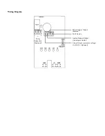

This device is a 3-wire sourcing type transmitter. Connect the positive dc voltage or the hot side of the ac voltage to the terminal marked
PWR
. The power supply common is connected to the terminal marked
COM
. The device is reverse voltage protected and will not
operate if connected backwards. This device has a half-wave type power supply so the power supply common is the same as the output
signal common. Therefore, several devices may be connected to one power supply and the output signals all share the same signal
common. Use caution when grounding the secondary of an ac transformer or when wiring multiple devices to ensure that the circuit
ground point is the same on all devices and the controller.
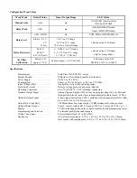
Several output signal options are available from the Air Quality Monitor depending on the model. The standard model is equipped with
an Analog Stepped Output (ASO) signal which is available on the terminal marked
ASO
. This signal is meant to drive a damper actuator
directly in four discreet steps relative to the OK, LOW, MID and HIGH pollution levels. The signal levels are completely adjustable
and each step can be set anywhere from 0 to 10 Vdc to accommodate any actuator that will accept a 0-10 Vdc control signal. Since all
steps are completely adjustable, the device can also drive a reverse acting actuator.
An optional output signal is available on the
LIN
terminal. This signal is jumper selectable for either a voltage output or 4-20 mA active
output. In voltage mode the output can also be jumper set for either 0-5 or 0-10 output voltage range. All of these options are clearly
indicated on the device circuit board. The 4-20 mA current output signal operates in the Active mode and does not require a loop power
supply. This means that
the signal current is generated by the Air Quality Monitor and must not be connected to a powered input
or device damage will result.
Check the controller Analog Input to determine the proper connection before applying power. Both the
current and voltage signals are referenced to the
COM
terminal. The analog output signal is typically connected directly to the Building
Automation System (B.A.S.) and used as a control parameter or for logging purposes.
A second optional signal is the relay output available on the
NO, COM
and
NC
terminals. Note that the relay COM terminal is NOT
connected to the signal COM terminal. The relay output is completely isolated and has both Normally Open (NO) and Normally Closed
(NC) signals. This signal can be used to directly control an alarm, a ventilation fan or may be connected to a digital input of the B.A.S.
for status monitoring.
Start-up
Verify that the Air Quality Monitor is properly wired and all connections are tight. Apply power to the device and note the status LEDs.
Initially the OK LED will be on and the AUTO LED will flash to indicate a four minute warm-up cycle to allow the sensor to reach
normal operating temperature.
The device will enter normal operation after the initial warm-up period. This will be indicated by the AUTO LED being lit and also
one pollution level LED being lit (OK, LOW, MID or HIGH).
The sensor is calibrated at manufacture to be suitable for use in average room conditions.
The sensor filter will accumulate dust over
a period of inactive time and the sensor must be allowed to burn-in before proper operation.
This time will vary depending on
the storage time but the unit will be suitable for pre-commissioning after about 30 minutes. If the device will be re-calibrated, the unit
should be powered for about three days before making final adjustments. This time is for the sensor output only and the ASO signal
levels may be set immediately after the warm-up cycle.
Operation
The Air Quality Monitor may be operated in two modes, either Automatic or Manual. It is recommended that the device be used in Auto
mode for most applications.
In general, the device compares the amount of contaminants in the air to a base level. The base level is established and adjusted
automatically for best results in the Auto mode or it can be entered manually by the user in the Manual mode of operation. The
comparison of sensor reading to the base level uses a scale factor to determine if the pollution level is considered ok, low, mid or high.
In Auto mode the scale factor is set by the user to control the device sensitivity for different operating environments. In Manual mode
the scale factor is factory set to a predetermined value and cannot be adjusted.
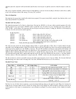
The operation of the device is best understood by relating the various operating points with respect to (wrt) either the 0-5 volt linear
output signal from the device (wrt-output) or to the internal sensor output signal (wrt-sensor) as applicable. Note that the internal sensor
signal is not available to the user but provides a good point of reference to explain the operation. The 0-5 volt output signal is used in
these examples but the 0-10 volt and 4-20 mA outputs are directly scaleable. Typically, the air quality sensor will output about 1.50
volts in clean air and about 4.00 volts in extremely contaminated air (such as when the sensor is close to a burning cigarette). The
following chart will help understand settings such as the scale factor, base level, relay parameters, etc.


