


Introduction
The Air Quality Monitor uses a tin dioxide semiconductor sensor based on the Taguchi principle to detect oxidizable gases and is
specially designed to have high sensitivity to gaseous organic materials which are components of indoor air pollutants. The sensor is
essentially a heated element inside a porous semiconductive tube. The tube has a large surface area and is able to freely absorb gas
molecules such that electron transfer occurs between the gas and oxygen molecules. This causes a relatively large increase in
conductivity for a small change in gas concentration. This change occurs within a few seconds and is completely reversible.
The sensor responds with varying degrees of sensitivity to a wide variety of gasses which include hydrogen, hydrocarbons, alcohols,
carbon monoxide, benzene, etc. Although the sensor does not detect carbon dioxide, it is still quite useful in human environments since
hydrocarbons, body odours and water vapors are emitted by breathing and perspiration. The levels of these other contaminants change
at roughly the same rate as the carbon dioxide and the sensor will track these other contaminants at approximately the same rate as the
carbon dioxide in occupied spaces.
The Air Quality Monitor may be used as either a stand-alone controller to detect levels of pollution and operate a clean-air damper
directly, or it may be used as a monitor where the analog output signal is transmitted to the Building Automation System for further
processing.
Many different environments can be controlled with careful adjustment of the device parameters so it functions equally well in a school
room where the air is to be kept very clean or a utility room where the fresh air requirements are not as stringent. The Air Quality
Monitor can be used to control intake dampers at an airport where jet fumes are periodic contaminants, automatically control exhaust
air on an assembly line where epoxies are used or a multitude of other applications.
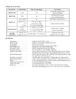
Some common detectable pollutants in decreasing order of sensitivity (most are easily detectable in quantities of 20 ppm or less).
Chemical
Symbol
Common Source
Methyl Ethyl Ketone
C
4
H
8
O
Solvents and cleaning products
Acetone
C
3
H
6
O
Solvents and organic synthesis
Ethyl Alcohol
C
2
H
6
O
Solvents and liquor fermentation
Formaldehyde
CH
2
O
Disinfectants and preservatives
Hydrogen
H
2
Used in synthetics
Methyl Alcohol
CH
4
O
Solvents, antifreeze and synthetics
Vinyl Chloride
C
2
HCl
Textiles and polymers
Hydrogen Sulfide
H
2
S
Water and putrefying matter
Methyl Chloride
CH
3
Cl
Solvents, paints and refrigerant
Benzene, Toluene, Xylene
C
6
H
6
, C
7
H
8
, C
8
H
10
Solvents and motor fuels
Trichloroethylene
C
2
HCl
3
Solvents and cleaning agents
Propane
C
3
H
8
Fuels and chemical synthesis
Carbon Monoxide
CO
Combustion of carbon
Freon-22
CHClF
2
Refrigerants and aerosols
Ammonia
NH
3
Solvents and refrigerants
Methane
CH
4
Decomposition and synthesis
Mounting
The AE type room sensor will install directly on a standard electrical box and should be mounted about five feet from the floor of the
area to be controlled. For best operation, do not mount the sensor near doors, opening windows, supply air diffusers or other known
air disturbances.
The D type duct sensor should be mounted on the outside of a return air duct with the air sampling tube inserted into the duct. Install
the sensor in an easily accessible location in a straight section of duct at least five feet from corners and other items that may cause
disturbances in the air flow. Avoid areas such as kitchen fume hoods where oil and grease may contaminate the sensor filter.
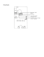
Wiring
Use 22 AWG shielded wiring for all connections and do not locate the device wires in the same conduit with wiring used to supply
inductive loads such as motors. Disconnect the power supply before making any connections to prevent electrical shock or equipment
damage. Make all connections in accordance with national and local codes.


