1
DESCRIPTION
1.1
PURPOSE
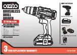
The machine is intended for driving in and loosening screws
and bolts as well as for tightening and loosening nuts within
the respective range of dimension.
1.2
OVERVIEW
Figure 1.
1
1/2" Drive (Coupler)
2
LED work Light
3
Switch trigger
4
Speed Selection
5
Reversing button
2
SAFETY
WARNING
Make sure that you do/obey all safety instructions.
Refer to Safety Manual.
3
INSTALLATION
3.1
UNPACK THE MACHINE
WARNING
Make sure that you correctly assemble the machine before
use.
WARNING
•
If the parts are damaged, do not use the machine.
•
If you do not have all the parts, do not operate the
machine.
•
If the parts are damaged or missing, speak to the service
center.
1. Open the package.
2. Read the documentation in the box.
3. Remove all the unassembled parts from the box.
4. Remove the machine from the box.
5. Discard the box and package in compliance with local
regulations.
3.2
INSTALL THE BATTERY PACK
Figure 2.
WARNING
•
If the battery pack or charger is damaged, replace the
battery pack or the charger.
•
Stop the machine and wait until the motor stops before
you install or remove the battery pack.
•
Read, know, and do the instructions in the battery and
charger manual.
1. Align the lift ribs on the battery pack with the grooves in
the battery compartment.
2. Push the battery pack into the battery compartment until
the battery pack locks into place.
3. When you hear a click, the battery pack is installed.
3.3
REMOVE THE BATTERY PACK
Figure 2.
1. Push and hold the battery release button.
2. Remove the battery pack from the machine.
4
OPERATION
WARNING
Always wear eye protection.
WARNING
Do not use any attachments or accessories not
recommended by the manufacturer of this product.
4.1
START THE MACHINE
Figure 3.
NOTE
The machine can not work until the reversing button is
pushed fully to the left or right. Do not operate the machine
at low speeds for extended periods of time.
1. Push the switch trigger to turn the machine ON (I).
4.2
STOP THE MACHINE
Figure 3.
1. Release the switch trigge to turn the machine OFF (O).
WARNING
Release the switch trigger and let the coupler to come to a
complete stop.
4.3
LED LIGHT
Figure
4
The LED light illuminates when the trigger is depressed.
It provides extra light for increased visibility.
4
English
EN
Содержание GD24IW400
Страница 2: ......
Страница 32: ...1 1 1 1 2 1 1 1 2 2 3 4 5 2 3 3 1 1 2 3 4 5 3 2 2 1 2 3 3 3 2 1 2 4 4 1 3 1 I 4 2 3 1 O 32 RU...
Страница 80: ...1 1 1 1 2 1 1 1 2 2 LED 3 4 5 2 3 3 1 1 2 3 4 5 3 2 2 1 2 3 3 3 2 1 2 4 4 1 3 1 ON I 4 2 3 1 OFF O 80 BG...
Страница 84: ...1 1 1 1 2 1 1 1 2 2 LED 3 4 5 2 3 3 1 1 2 3 4 5 3 2 2 1 2 3 3 3 2 1 2 4 4 1 3 1 ON 4 2 3 1 OFF O 84 EL...
Страница 111: ......
Страница 112: ......


