background image

Greenlee Textron / Subsidiary of Textron Inc.

5

4455 Boeing Dr., Rockford, IL 61109-2988    815/397-7070

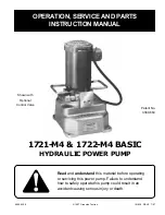
1721-M4 Basic & 1722-M4 Basic Hydraulic Power Pumps

Operation

The pump is designed to operate at 10,000 psi. For
continuous service, such as production work, the
pressure intermittently, should not exceed 6,000 psi.
This limitation is for the protection of the motor only.

Before operating the pump, check the following proce-
dures to assure proper service:

1.

Check proper power connections and tightness of
hose connections before starting pump.

2.

Check hydraulic oil with dip stick (53). Oil should be
within 1/2” of reservoir top.

3.

Start motor and allow pump to idle a few minutes.
This will allow the hydraulic oil to work into moving
parts and give prime to pump.

Service

Filling the Oil Reservoir

In order for the pump to operate properly, the oil
reservoir must be kept filled with a good grade of light
hydraulic oil:  Greenlee 905 0806.8 hydraulic oil or
equivalent. Eight quarts are required, of which 6-1/4
quarts are usable. A minimum of 1-3/4 quarts must be
at the bottom of the reservoir at all times during the
operation. Be sure that the complete operation does not
require more than the usable amount of oil.

To refill or add oil to the reservoir, proceed as follows:

1.

Remove vent unit from top of reservoir.

2.

Add oil to within 1/2" of top of reservoir when ram is
retracted.

3.

Install vent unit securely.

Do not use synthetic fluids with poor lubricating
qualities such as brake fluids. The result is perma-
nent damage to the pump.

Before operating pump, be sure vent unit is not
clogged.

Flushing the System

As long as the pump is used as outlined in the operating
instructions, trouble-free performance can be expected.
To maintain this performance, it is absolutely essential
that dirt or other foreign matter be kept out of the sys-
tem, as this is the most common cause of hydraulic
system failure. When opening the pump for any reason,
such as making pipe connections, adjusting pressure or
any repair, exercise extreme care in cleanliness and use
clean tools and cloths. If at any time dirt is suspected to
have entered the system, the entire oil system should be
flushed as follows:

1.

Drain oil from reservoir.

2.

Fill reservoir with any recommended flushing oil or
clean kerosene and operate pump. Work the control
handle back and forth several times during flushing
to wash all foreign particles from the control valve
unit.

3.

Drain flushing oil or kerosene from reservoir and
refill with new oil.

Motor Maintenance

Greenlee recommends the 1721-M4 and 1722-M4 be
sent to a qualified Greenlee Service Center or to the
manufacturer when in need of repair.

Do not operate pump for long periods of time. The
system is not designed to operate with flushing oil
or kerosene.

Содержание 1722-M4

Страница 1: ...7 97 1721 M4 1722 M4 BASIC HYDRAULIC POWER PUMP Shown with Optional Control Valve Patent No 3 389 660 Read and understand this material before operating or servicing this power pump Failure to understand how to safely operate this pump could result in an accident causing serious injury or death ...

Страница 2: ...ut important safety precautions It means ATTENTION Become alert Your personal safety is involved Read the message that follows and be alert to the possibility of personal injury or death Hazards or unsafe practices which if not avoided COULD result in minor personal injury or property damage Hazards or unsafe practices which if not avoided COULD result in severe personal injury or death Immediate ...

Страница 3: ...ck for leaks Depressurize hydraulic system before disconnecting the hose Inspect pump hoses couplers and fittings for wear or damage Replace worn damaged or missing components with Greenlee replacement parts Do not twist kink curl paint or cut the hydraulic hoses Wear eye protection when operating this equipment Disconnect the pump from the power supply rotate the release valve lever to AUTO RELEA...

Страница 4: ...e This two mode operation is a time saving feature that allows fast ram approach and an automatic switchover when pressure exceeds 200 psi The pumping unit is a single piston radial type capable of developing 10 000 psi An integral unloading check valve unloads the high pressure stage of the pump and permits the motor to be restarted while maintaining the load These models have an externally mount...

Страница 5: ...nit from top of reservoir 2 Add oil to within 1 2 of top of reservoir when ram is retracted 3 Install vent unit securely Do not use synthetic fluids with poor lubricating qualities such as brake fluids The result is perma nent damage to the pump Before operating pump be sure vent unit is not clogged Flushing the System As long as the pump is used as outlined in the operating instructions trouble f...

Страница 6: ...y Qt Pump motor will not start Power cord not sufficiently Check for tight connections connected Power cord cut Replace power cord Defective motor or switch Replace or repair Fuse in wall box is blown Replace fuse Will not pump oil Not primed Run pump for a few minutes tipping unit from side to side Sticking plunger Replace plunger bushing 8 9 Plugged up screens Clean or replace intake screen 24 D...

Страница 7: ...8 815 397 7070 1721 M4 Basic 1722 M4 Basic Hydraulic Power Pumps 62 60 61 52 73 72 56 56 69 68 1 8 ALLEN WRENCH 57 59 70 NOTE REMOVE SET SCREW BEFORE REMOVING MOTOR 67 74 62 64 54 63 65 58 55 53 A 62 43 10 50 9 25 12 00 10 75 SERIAL NO LOCATION 18 21 1721 SERIES 19 93 1722 SERIES 75 ...

Страница 8: ...d IL 61109 2988 815 397 7070 1721 M4 Basic 1722 M4 Basic Hydraulic Power Pumps Parts 35 30 10 24 18 15 12 17 16 11 14 39 40 27 10A A A B B SECTION A A SECTION B B 40 19 25 4 22 37 26 20 1 2 70 62 58 20 6 32 5 34 3 4 2 28 38 23 36 29 26 7 33 9 8 22 41 13 21 24A 096 106 ...

Страница 9: ...t 1 22 500 6111 9 Spring Compression 1 23 501 4865 6 Spring Compression 1 24 502 1175 7 Screen Intake 1 24A 501 6599 2 Screen Intake replaced by 24 1 25 905 0014 8 O Ring 5 8 x 3 4 x 1 16 1 26 905 0436 4 Ball 9 32 Grade 1 Chrome Steel 2 27 905 0490 9 Nipple Intake replaced by 10 1 28 905 0677 4 Ball 5 32 Grade 1 Chrome Steel 1 29 905 0681 2 Ball 3 8 Grade 1 Chrome Steel 1 30 905 1526 9 Washer 8 Hi...

Страница 10: ...1 4 Cup Point Socket Head Set 1 69 918 5117 3 Connector 1 70 905 1474 2 Screw 3 8 24 NF x 2 1 2 Socket Head Cap 4 72 918 5264 1 Cord 10 Foot 1 73 918 5284 6 Switch Toggle 1 74 918 5183 1 Motor 1 HP Electric 1 GE Motor 5KC43PG782T Franklin Motor 1112050101 Dayton 6K674 Parts Hydraulic Power Pumps cont d 1721 M4 Basic 501 8320 6 1722 M4 Basic 501 8355 9 Service Parts GE FRANKLIN DAYTON Greenlee 918 ...

Отзывы: