background image

5

Ceiling Exhaust and Inline Fans

Wire the Fan

115 & 277 Volt

Black wire is “Hot”
White wire is “Neutral”
Green wire is “Ground”

220 - 240 Volt

Black wire is “Hot”
White wire is “Hot”
Green wire is “Neutral/Ground”

Fig. 7a

Fig. 7b

1.  Remove wiring cover. 

If fan/light combination 
is being used, make 
sure the fan plug is 
connected to the fan 
receptacle and the light 
plug is connected to 
the light receptacle, 
shown in Fig. 6. 
Using proper wire 
connectors, wire the fan as shown in Fig. 7a.  
For wiring of light proceed to Fig. 7b.

2.  Push all wiring into the unit’s cover and replace  

wiring cover.

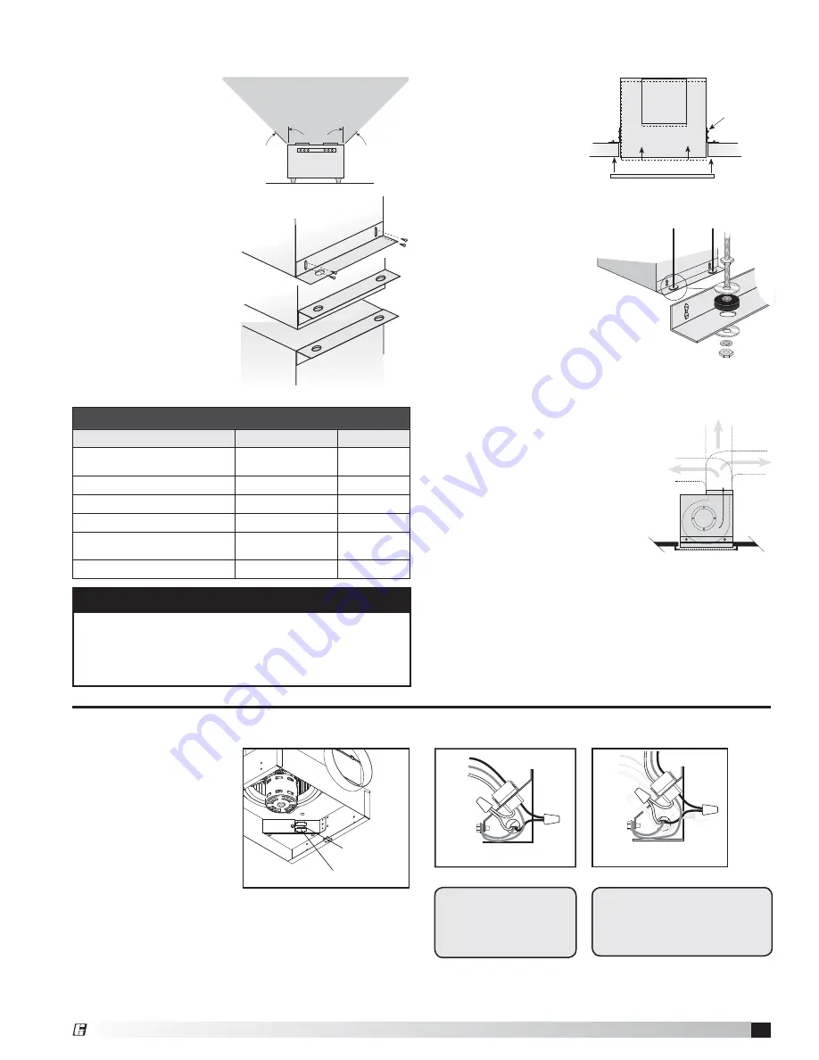
For Frame Construction:


Position unit between 
joists. Position brackets 
such that bottom 
edge of housing will 
be flush with finished 
ceiling, and tighten the 
adjustable mounting 
brackets, shown in  
Fig. 3.

For Hanging 
Installations:  

Use Greenheck’s 
optional vibration 
isolator kit Part Number 
VI Kit. Using the fan’s 
standard adjustable 
mounting brackets and 
10 by 32 threaded rod 
(by others), hang unit as 
shown in Fig. 4.

Install the Fan

1. For best 

performance, 
choose a location 
with the shortest 
possible duct run 
and minimum 
number of elbows. 
Do not mount near 
cooking equipment, as 
shown in Fig. 1.

2. Attach adjustable 

mounting brackets 
to fan, but leave the 
screws loose until 
proper height is 
determined, shown 
in Fig. 2. Cut hole to 
dimensions shown  
in table below:

3.  Installation of ductwork  

is critical to the performance 
of the fan, shown in Fig. 5. 
Straight ductwork (1) or 
ductwork that turns in 
the same direction as the 
wheel (2) is recommended. 
Ductwork turning opposite 
the wheel direction (3) will 
cause turbulence and back 
pressure resulting in poor 
performance.

4.  Slide ductwork over the fan’s discharge collar and 

securely attach it with sheet metal screws. 

Make sure the screws do not interfere with damper 
operation. Check damper to make sure it opens freely.

Top Mount

Bottom Mount

Brackets can be
used in either
position to adapt to
most mounting
situations

Bottom Mount

Fig. 2

Slots in the
brackets
allow fine
adjustment
for flush
fit with
wall/ceiling
opening

AIRFLOW

1

(GOOD)

3

(POOR)

2

(GOOD)

Fig. 5

45°

45°

Do not install 

fan in this area

Ceiling Openings

Sizes

Fan or Fan/Light

Fan/CRD

SP-A50, A70, A90
SP-A110, A125, A190

10

7

8

 x 13

3

8

11

1

8

 x 13

7

16

SP-A200, A250, A290, A390

12

1

8

 x 14

1

4

12

1

4

 x 14

3

8

SP-A700

23

3

4

 x 11

3

4

24

1

8

 x 12

1

4

SP-A410, A510, A710, A780

14

3

4

 x 18

3

8

14

7

8

 x 18

7

16

SP-A900, A1050, A1410, 
A1550

14

3

4

 x 24

14

7

8

 x 24

1

8

SP-B 50 - 200

14

1

8

 x 11

3

4

14

3

8

 x 12

1

4

Fig. 3

Fig. 4

NOTE

Model SP-A 50-90 are standard with a round duct. 
Should Model SP-A 110-190 require a round duct, 
Model RDC (Round Duct Connector) may be ordered 
from Greenheck for field installation

.

Fig. 1

Fig. 6

Light

Fan

Fan Outlet (top)

Light Outlet (bottom)

®

Содержание CSP

Страница 1: ...necting means to prevent power from being switched on accidentally When the service disconnecting means cannot be locked securely fasten a prominent warning device such as a tag to the service panel Installation work and electrical wiring must be done by qualified person s in accordance with all applicable codes and standards including fire rated construction Sufficient air is needed for proper co...

Страница 2: ...A Models Only A 50 500 710 780 Models Remove the two screws holding the power assembly in and pull power assembly out Rotate power assembly 180 degrees and put back into fan Use the same screws to reattach power assembly to fan housing Flip fan over and remove the four screws holding the discharge duct and damper assembly Exchange the assembly with plate mounted on top of fan as shown in these ill...

Страница 3: ...iation damper has an electrical plug in it The electrical plug must be inserted into the fan Make sure the electrical wire will not interfere with damper operation as shown in figure below Discharge Installation SP A 50 90 Models A 50 510 710 780 Models Wires from lighted grille Wires to ceiling fan Do not allow interference in this area A 700 900 1550 Models SP A Box Slot Plastic SP A Duct Adapter...

Страница 4: ...two SP B mounting tabs fully engage into the two SP B box mounting slots 1 2 OPTIONAL Align the pins on the TR 6x4 adaptor to the duct pin hole on the SP B 6 inch duct Push until the adaptor snaps into place 3 SP B Box Scroll Slots SP B Box Mounting Tabs SP B Box Mounting Slots TR 6x4 Pin TR 6x4 PN 473324 SP B 6 inch Plastic Duct PN 474433 SP B Plastic Duct Pin Hole SP B Box Scroll Tabs ...

Страница 5: ...height is determined shown in Fig 2 Cut hole to dimensions shown in table below 3 Installation of ductwork is critical to the performance of the fan shown in Fig 5 Straight ductwork 1 or ductwork that turns in the same direction as the wheel 2 is recommended Ductwork turning opposite the wheel direction 3 will cause turbulence and back pressure resulting in poor performance 4 Slide ductwork over t...

Страница 6: ...wn are UL and cUL listed E 33599 Attach the Grille 1 If lighted grille is being used plug wire into fan socket If lighted grille and ceiling radiation damper are being used plug wire from lighted grille into ceiling radiation damper socket Do not plug wire directly into the fan socket Make sure the wire does not interfere with the ceiling radiation damper operation 2 Attach grille with two screws ...

Страница 7: ... cleaned periodically to maintain performance Greenheck offers washable aluminum mesh filters specifically designed for these fans Please consult our SP CSP catalog for more information Flex Duct Connections Fiberglass Ductboard Remote Mounted Correct Low Sound Installation Incorrect SP and SP C Mounted Directly Overhead CSP and SP C Converted to Inline General Maintenance Suggestions Model SP CSP c...

Страница 8: ...in the Library under Warranties Greenheck SP and CSP catalog provides additional information describing the equipment fan performance available accessories and specification data Phone 715 359 6171 Fax 715 355 2399 E mail gfcinfo greenheck com Website www greenheck com Our Commitment AMCA Publication 410 96 Safety Practices for Users and Installers of Industrial and Commercial Fans provides additio...

Отзывы: