Microprocessor Controller for DOAS
37
®
The expansion board is an I/O module than can be used to monitor additional statuses or provide commands from
large board controller. It allows the user to view and control:
•
6 Universal Inputs (Digital Input*,
NTC, 0/1VDC, 0/10VDC, 0/20mA,
4/20mA, 0/5VDC)
*Only dry to ground contacts
can be utilized for digital inputs.
Applying voltage will result in
damage to the I/O expansion board.
•
4 Analog Outputs (VDC)
•
6 Digital Outputs
The inputs and outputs can be
monitored and controlled by the Building
Management System. Reference Points
List for detailed point information.
In order for the controller to communicate with the c.pCOe, several parameters must be adjusted. If you have
a c.pCOe installed from the factory, the controller is already set up for communication with the main controller.
The factory password is required for expansion board and I/O configuration updates. Consult factory for I/O
configuration changes.
Appendix: I/O Expansion Board (c.pCOe) Quick Start
Setup
1
2
3
4
5
6
7
8
9
10
11
12
13
14
15
19.2 K
9.6 K
38.4 K
57.6 K
CAREL
M
odbus
ON
OFF
A
d
dr
ess
Ex
t.
Pr
ot
Baud
A
ddr
ess
Ex
t
Baud
Pr
ot
24 VAC
Power
Digital
Outputs
Universal
Inputs
Analog
Outputs
Configuring the I/O Type
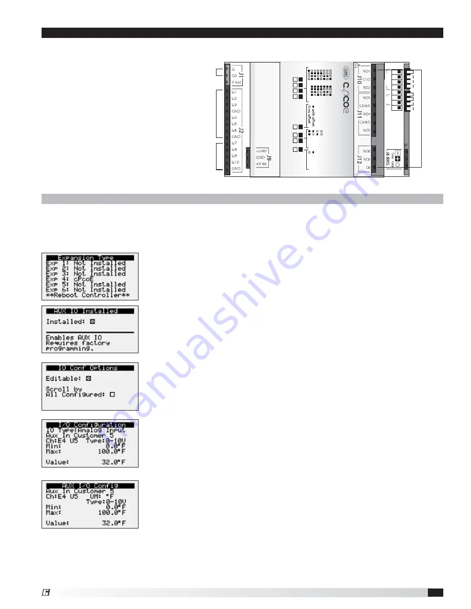
- In order to edit and configure the I/O configuration of
the unit, go to Ctrl Variables/Advanced/I/O Configuration. The user must enable
the Editable option for configuring I/O points. If configuring a new I/O point, ‘Scroll
by All Configured’ must be deselected to view all I/O options.
Enabling the pCOe in the Main Controller.
- To enable the c.pCOe expansion
I/O module, go to Ctrl Variables/Advanced/Unit Config. User will have to enter
the Factory Password to make any edits at this point. Consult factory for factory
password and configuring the expansion board. The expansion board must be
enabled to configure spare I/O points. Once enabled, the user must reboot the
controller. See screens to the left for expansion board enable points.
Change or Update the I/O Point
- Once the editable option is selected, the
user must scroll to the I/O Configuration Menu. At this menu the desired I/O
type can be selected. Once selected the user can configure the desired channel
at the expansion board. The channel will have an ‘E’ designation for expansion
board. Aux In Customer 1–6, Aux Analog Out 1-4, and Aux Digital Out 1-6 will be
allocated for the I/O expansion board. See example to the left.
Viewing c.PCOe Auxiliary Values
– Once the expansion board I/O is configured,
the user can view and/or change the I/O type by navigating to Ctrl Variables/Aux
I/O Config.


