


48
K.
Reinstall burner and mixer gasket and position
mixer assembly over studs. Install five (5) nuts but
do not tighten. Reinstall igniter and igniter gasket
and fasten with two (2) screws. Use care when
installing the igniter. Tighten five (5) nuts holding
mixer assembly.
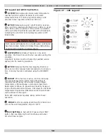
L. Connect:
• Gas line to gas valve
• Condensate drain line to boiler
• Pressure switch hose to gas valve
• Air by-pass to mixer
•
1 ½” x 2” flexible coupling to air inlet and make
sure to put air baffle back to correct position
• Igniter wires
• Gas valve wires
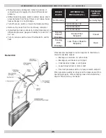
3.
Visually inspect condensate lines leading from boiler
sections and vent pipe connector to condensate trap.
Refer to repair parts diagrams. Any foreign material or
debris visible in condensate lines needs to be cleaned
out as follows:
A. Disconnect condensate drain lines from condensate
trap.
B. Remove condensate trap and drain all water from
trap.
C.
Disconnect condensate lines from fitting on bottom
of boiler and vent pipe connector.
D. Run cold water through condensate lines and trap
to thoroughly flush out any sediment or debris.
E. Reinstall condensate trap and condensate lines.
F. Follow instructions under “Near Boiler Piping” for
filling condensate trap with water.
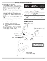
4.
Inspection of flue connector requires following steps. Refer
to repair parts diagram.
A. Loosen the clamp on the draft inducer end of the
2” vent pipe connector that connects the vent
to the draft inducer. Disconnect (unplug) wiring
harness from draft inducer motor and draft inducer
temperature safety switch. Remove four (4) bolts
that attach draft inducer to flue connector.
B.
Remove draft inducer and gasket from top of flue
connector.
C.
Inspect interior of flue connector. Any buildup of
sediment or aluminum oxide on inside surface must
be cleaned. Position draft inducer gasket and draft
inducer and fasten with four (4) screws. Be sure to
connect ground wire from draft inducer motor to
one of four mounting screws.
D. Connect wiring harness leads to draft inducer motor
and draft inducer temperature safety switch.
E. Connect vent pipe connector to draft inducer outlet.
MAINTENANCE AND CLEANING
Annual Examination And Cleaning Of Boiler
Components
DANGER
Before servicing, turn off electrical power to boiler
at service switch. Close manual gas valve to turn
gas supply OFF to boiler. Failure to comply will result
in death or serious injury.
!
NOTICE
Have qualified service agency perform the following
service procedures. Boiler owner should not attempt
these procedures.
1.
Before Servicing, turn off electrical power to boiler at
service switch. Close manual gas valve to turn off gas
supply to boiler.
2.
Cleaning Flue passages between boiler sections.
A. Any buildup of sediment or aluminum oxide (white
powdery or flaky substance) in flue passages must
be cleaned as follows.
B.
Remove jacket front and top panels. Disconnect
condensate drain line from barbed fitting on bottom
of boiler. Keep open end of drain line above water
level in condensate trap to prevent trap from
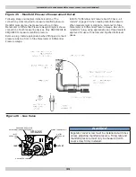
draining. Disconnect pressure switch hose from
barbed fitting on gas valve. Disconnect 1½ x 2”
flexible coupling from air inlet. Disconnect air by-
pass (½” transparent vinyl tube) from bottom of
mixer.
C.
Remove air baffle from ½” x 2” flexible coupling
and clean air baffle if necessary. Refer to repair
parts diagram, mixer and pressure switch
assembly.
D.
Confirm manual gas valve is closed and disconnect
gas line to gas valve at union. Disconnect wires to
gas valve and igniter.
E.
Loosen but do not remove five (5) nuts attaching
mixer assembly to boiler. Remove two (2) igniter
screws and remove igniter.
F.
Remove five (5) nuts and remove mixer assembly.
Remove burner and mixer gasket.
G. Aluminum oxide deposits are water soluble and
may be rinsed away with spraying or running
water. Before rinsing, connect a ½” I.D. hose to
barbed fitting on bottom of boiler and run hose to
bucket or drain.
H. After rinsing, remove any remaining loosened
sediment using shop vacuum with snorkel
attachment.
I.
Inspect burner for any foreign matter in flame
ports or inside burner. Any foreign matter should
be removed by blowing with compressed air or
vacuuming.
J. Inspect interior of mixer for any signs of sediment
or aluminum oxide and clean if necessary.
NOTICE
Verify proper operation after servicing.
Содержание GM90-100
Страница 12: ...12 NEAR BOILER PIPING Figure 2 Single Zone Boiler Piping SAFETY RELIEF VALVE SEE PAGE 18 FOR REQUIREMENTS...
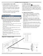
Страница 31: ...31 Figure 20 Field Wiring Connections ELECTRICAL WIRING SAFETY RELIEF VALVE SEE PAGE 18 FOR REQUIREMENTS...
Страница 33: ...33 Figure 22 Ladder Diagram for Figure 22 ELECTRICAL WIRING...
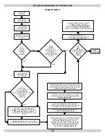
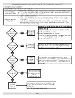
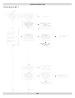
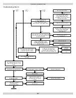
Страница 52: ...52 Troubleshooting Chart 1 TROUBLESHOOTING...
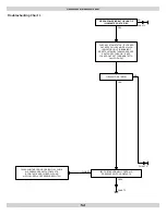
Страница 53: ...53 Troubleshooting Chart 2 TROUBLESHOOTING...
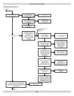
Страница 55: ...55 Troubleshooting Chart 4 TROUBLESHOOTING...
Страница 63: ...63 NOTES...


