


23
5.
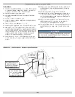
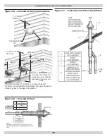
See Figure 12 thru Figure 17, Pages 24 thru 26
for combustion air and vent pipe roof and sidewall
termination. Roof termination is preferred. Combustion
air and vent pipes must terminate together in same
atmospheric pressure zone as shown.
6.
Construction through which vent and air intake pipes
may be installed is maximum 24 inches, minimum ¼”
thickness.
7.
Optional- Rotate draft inducer (blower) 90° or 180°
to orient vent connection towards right side or rear.
Remove blower mounting screws, re-orient blower.
Reinstall mounting screws. Do not overtighten screws.
8.
Pitch combustion air and vent piping back to boiler at
minimum ¼” per ft. (21 mm/m) from intake and vent
terminals so all moisture in combustion air and vent
piping drains to boiler. Pitch pipes continuously with no
sags or low spots where moisture can accumulate and
block flow of air or flue gas. Combustion air and vent
pipes must be airtight and watertight.
9.
Consider following when determining appropriate
location for termination of combustion air and vent
piping.
• Position termination where vent vapors will not damage
plants/shrubs or air conditioning equipment.
• Position termination as to not be effected by wind eddy,
air born leaves, snow, or recirculated flue gases.
•
Position termination where it will not be subjected to
potential damage by foreign objects, such as stones,
balls, etc..
• Position termination should where vent vapors are not
objectionable.
• Place vent on wall away from prevailing wind. Locate or
guard vent to prevent accidental contact with people or
pets.
• Terminate vent above normal snow line. Avoid locations
where snow may drift and block vent. Ice or snow may
cause boiler to shut down if vent becomes obstructed.
•
Under certain conditions, flue gas will condense, forming
moisture, and may be corrosive. Take steps to prevent
building materials at vent from being damaged by
exhaust of flue gas.
• Vent shall not terminate where it may cause hazardous
frost or ice accumulations on adjacent property surfaces.
10.
Venting Requirements:
• Venting system shall terminate at least 3 ft. (0.9m)
above any forced air inlet (except boiler’s combustion
air inlet) within 10 ft.(3m).
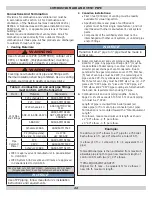
COMBUSTION AIR AND VENT PIPE
Table 5 - Combustion Air And Vent Piping Lengths - Total Equivalent Length
BOILER
SIZE
2” PIPE MINIMUM
VENTING
2” PIPE MAXIMUM
VENTING
3” PIPE MINIMUM
VENTING
3” PIPE MAXIMUM
VENTING
100
2 FEET
21 FEET
15 FEET
92 FEET
75 & 50
2 FEET
26 FEET
20 FEET
112 FEET
NOTE: Follow venting lengths strictly, to avoid nuisance pressure switch trips.
• Venting system shall terminate at least 12 in. from any
air opening into any building.
• Vent bottom shall be located at least 12 in. above
grade.
• Termination of the vent shall be not less than 7 ft.
(2.1m) above adjacent public walkway or paved
driveway.
• Vent terminal shall not be installed closer than 3 ft.
from inside corner of L shaped structure.
• Vent termination should be kept at least 3 ft. away
from vegetation.
• Venting system shall terminate at least 4 ft.
horizontally from, and in no case above or below,
unless 4 ft. (1.22m) horizontal distance is maintained,
from electric meters, gas meters, regulators, and relief
equipment.
• Canada only.
• Venting system shall terminate at least 6 ft. (1.83m)
horizontally from, in no case above or below, unless a
6 ft. (1.83m) horizontal distance is maintained, from
electric meters, gas meters, regulators, and relief
equipment.
• Vent shall not terminate within 6 ft. (1.8m) of
mechanical air-supply inlet to any building.
• Vent shall not terminate above regulator within 3
ft. (900 mm) horizontally of vertical center line of
regulator vent outlet to maximum vertical distance of
15 ft. (9.5m).
• Vent shall not terminate within 1 ft (305mm) for
inputs up to and including 100,000 btu/hr and 3 ft.
(900mm) for inputs exceeding 100,000 btu/hr of
window or door that can be opened in any building, or
any non-mechanical air-supply inlet to any building, or
of combustion air inlet of any other appliance.
• Vent shall not terminate underneath veranda, porch
or deck unless,
(a) veranda, porch or deck is fully open on minimum of
two sides beneath floor, and
(b) distance between top of vent termination and
underside of veranda, porch or deck is greater than
1 ft. (300mm).
See figures 12 and 13 and 14 for two pipe terminations.
See figures 15, 16 and 17 for concentric vent terminations.
Содержание GM90-100
Страница 12: ...12 NEAR BOILER PIPING Figure 2 Single Zone Boiler Piping SAFETY RELIEF VALVE SEE PAGE 18 FOR REQUIREMENTS...
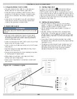
Страница 31: ...31 Figure 20 Field Wiring Connections ELECTRICAL WIRING SAFETY RELIEF VALVE SEE PAGE 18 FOR REQUIREMENTS...
Страница 33: ...33 Figure 22 Ladder Diagram for Figure 22 ELECTRICAL WIRING...
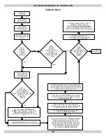
Страница 52: ...52 Troubleshooting Chart 1 TROUBLESHOOTING...
Страница 53: ...53 Troubleshooting Chart 2 TROUBLESHOOTING...
Страница 55: ...55 Troubleshooting Chart 4 TROUBLESHOOTING...
Страница 63: ...63 NOTES...


