


BACnet Gateway Kit for Central Air Conditioners
13
Fire
Vent
Electricity
Lift
BMS
Lighting
Internet(BACnet/IP Protocal)
COM2 COM1 COM2
COM2
COM1
COM2
COM2
COM1
COM2
ID Unit 1
Soldering
Point
OD Unit
Control
Cabinet
L1
L2
L2
L1
L1
L2
ID Unit 2
ID Unit 16
ID Unit 1
ID Unit 2
ID Unit 16
ID Unit 1
ID Unit 2
ID Unit 16
Commun-module1
Commun-module 4
WEB Client
L3
HUB
L3
Intranet(BACnet/IP Protocol)
Other BACnet
Gateway
BACnet
Gateway
BACnet
Gateway
Soldering
Point
Soldering
Point
OD Unit
OD Unit
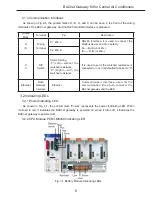
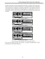
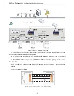
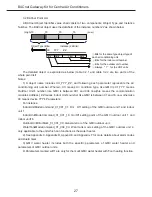
Fig.3-6
BACnet Network Topology
1) The communication module shown above is just taken as example, and always see the real
communication module for the actual interfaces.
2) As shown in the figure above, “L3” represents the universal communication line between
RJ45 interfaces.
3) The Web Server function provided by BMS(BACnet/IP) and BACnet gateway can be used at
the same time.
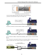
3.3.4 Connection between the BACnet Gateway and the Upper Communication
Device
3�3�4�1 Interface Connection
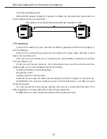
RJ45 Interface Connection with Parallel Line
Содержание MG30-24/D1(B)
Страница 5: ...中央空调 BACnet 网关套件安装使用说明书 3 ...
Страница 33: ...BACnet Gateway Kit for Central Air Conditioners 17 4 5 6 ...


