background image

73

Rooftop Packaged

Service Manual

Apply to 3, 4, 5Ton:

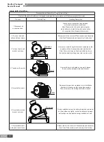
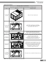
Disassembly and Assembly of Supply Blower Motor

Remark: Make sure that the unit is stopped running and power supply is cut off before removal of the motor.

Process

Pictorial View

Handling Description

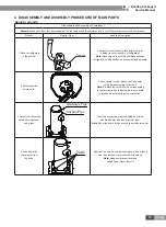
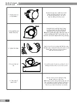
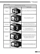
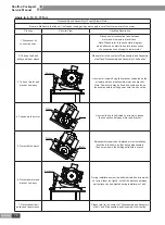
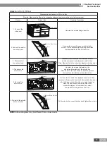
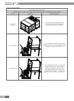
1.Take out the side plate.

Side Plate

Unscrew the screws fixing side plate .Lift 

the handles,slightly pulling it outwards and 

downwards to take out the side plate.

2. Disconnect all 

connection lines.

Disconnect all connection lines between 

motor and elements in electric box .

Note:Please refer to the schematic diagram 

which adhered on electric box for disconnection 

of connection lines of supply blower motor.

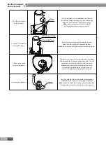
3. Disassemble the 

whole fan sub-assy.


Bolts

Bolts

Pull the power cord of motor through rubber ring to 

indoor. Unscrew the bolts fixing fan sub-assy (indicated 

by the arrows) ,and then take the fan sub-assy out.

Note: Power cord may be fixed by bundles,so loose 

the bundles before pulling power cord to indoor.

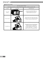
4. Loose connection 

between fan rotor 

shaft and fan blade.


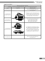
Screw

Unscrew the holding screw of fan (indicated by the 

arrows) to loose connection between motor shaft and fan.

Note: Fix fan blade when unscrewing hoiding 

nut of fan blade to avoid blade from rotating 

and thereby injury to people is caused.

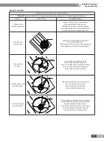
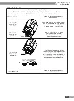
5. Remove the motor 

and bracket sub-assy.


Bolts

Unscrew fixed bolts of motor (indicated by the 

arrow) and then remove motor and bracket.

Note: Please mark relative installation location between 

motor and fan to ensure enough length of motors 

power cord from electric box after re-installation.

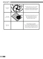
6. Take down the motor.


Unscrew holding bolt(indicated by the arrow) of motor 

bracket with a wrench to separate motor and bracket.

Note: Please mark relative installation location between 

motor bracket and motor before disassembly of motor to 

avoid installation mistake upon re-installation of motor.

Содержание EJ51000061

Страница 1: ...ROOFTOP PACKAGED SERVICE MANUAL T3 R22 50 60Hz GC201205...

Страница 2: ...ON POSITIONS 21 1 2 MATTERS NEED ATTENTION 21 1 3 DIMENSION 24 1 4 INSTALLATION CLEARANCE DATA 28 2 DRAIN PIPING WORK 31 2 1 INSTALLATION PROCEDURE 31 2 2 MATTERS OF ATTENTION 31 3 ELECTRIC WIRING WOR...

Страница 3: ...1 Rooftop Packaged Service Manual PRODUCT PRODUCT...

Страница 4: ...V 3Ph 50Hz 8 R22 GK H08TC1AM EJ51000311 380 415V 3Ph 50Hz 10 R22 GK C10TC1AF EJ51000061 220V 3Ph 60Hz 10 R22 GK C10TC1AM EJ51000240 380 415V 3Ph 50Hz 10 R22 GK H10TC1AM EJ51000331 380 415V 3Ph 50Hz 13...

Страница 5: ...red when they leave the factory ready to be used for a side supply side return application If a bottom supply bottom return application is desired you simply remove the two panels from the bottom of t...

Страница 6: ...1030 1030 970 Compressor Type Scroll Scroll Scroll Quantity 1 1 1 Oil type SAY56T SAY56T SAY56T Outdoor Coil Type Aluminum fin copper tube Face Area sq ft m2 8 06 0 75 8 23 0 765 7 85 0 73 Row FPI 1...

Страница 7: ...0 7 Motor rpm rpm 1090 1090 Compressor Type Scroll Scroll Quantity 1 1 Oil type SAY56T L DRC B56 Outdoor Coil Type Aluminum fin copper tube Face Area sq ft m2 8 4 0 78 10 76 1 Row FPI 2 16 2 16 Outdo...

Страница 8: ...rpm 1220 1220 Compressor Type Scroll Scroll Quantity 1 1 Oil type SAY56T SAY56T Outdoor Coil Type Aluminum fin copper tube Face Area sq ft m2 7 96 0 74 7 96 0 74 Row FPI 1 16 1 16 Outdoor Fan Type Ax...

Страница 9: ...pe Scroll Scroll Quantity 1 2 Oil type SAY56T SAY56T Outdoor Coil Type Aluminum fin copper tube Face Area sq ft m2 10 75 1 00 16 1 49 Row FPI 2 16 2 16 Outdoor Fan Type Axial fan Axial fan Quantity 1...

Страница 10: ...pe Scroll Scroll Quantity 1 2 Oil type SUNISO 4GSD SAY56T Outdoor Coil Type Aluminum fin copper tube Face Area sq ft m2 11 3 1 05 16 1 49 Row FPI 2 16 2 16 Outdoor Fan Type Axial fan Axial fan Quantit...

Страница 11: ...mpressor Type Scroll Scroll Quantity 2 2 Oil type SAY56T SUNISO 4GSD Outdoor Coil Type Aluminum fin copper tube Face Area sq ft m2 19 91 1 85 19 91 1 85 Row FPI 2 16 2 16 Outdoor Fan Type Axial Fan Qu...

Страница 12: ...ype Scroll Scroll Quantity 2 2 Oil type Mineral 160P SAY56T Outdoor Coil Type Aluminum fin copper tube Face Area sq ft m2 26 16 2 43 26 16 2 43 Row FPI 2 16 2 16 Outdoor Fan Type Axial fan Axial fan Q...

Страница 13: ...essor Type Scroll Scroll Quantity 2 2 Oil type Mineral 160P Mineral 160P Outdoor Coil Type Aluminum fin copper tube Face Area sq ft m2 26 16 2 43 34 11 3 17 Row FPI 2 16 2 14 Outdoor Fan Type Axial fa...

Страница 14: ...ressor Type Scroll Scroll Quantity 2 2 Oil type Mineral 160P Mineral 160P Outdoor Coil Type Aluminum fin copper tube Face Area sq ft m2 26 16 2 43 34 11 3 17 Row FPI 2 16 2 14 Outdoor Fan Type Axial f...

Страница 15: ...il type Mineral 160P POE 160SZ POE 320SZ Mineral 160P Outdoor Coil Type Aluminum fin copper tube Face Area sq ft m2 34 11 3 17 34 11 3 17 34 11 3 17 Row FPI 2 14 2 14 2 14 Outdoor Fan Type Axial Fan A...

Страница 16: ...Compressor Type Scroll Scroll Scroll Quantity 1 2 2 Oil type SAY56T SAY56T SAY56T Outdoor Coil Type Aluminum fin copper tube Face Area sq ft m2 11 3 1 05 19 91 1 85 19 91 1 85 Row FPI 2 16 2 16 3 16...

Страница 17: ...40 1440 Compressor Type Scroll Quantity 2 2 Oil type Mineral 160P Mineral 160P Outdoor Coil Type Aluminum fin copper tube Face Area sq ft m2 24 57 2 283 34 11 3 17 Row FPI 3 16 3 16 Outdoor Fan Type A...

Страница 18: ...l Fan Quantity 2 2 Diameter inch 31 69 31 69 Drive Type Direct Motor output Hp 3 3 Motor rpm rpm 940 940 Dehumidifying l h 23 1 30 Drain Connection Size inch 1 1 Refrigerant Refrigerant charge kg lbs...

Страница 19: ...255 8 4 26 95 200 190 GK C03TC1AK 1PH 220V 50Hz 1 17 130 1 9 3 7 32 30 GK C04TC1AM 3Ph 380V 415V 50Hz 1 8 06 73 1 9 3 7 16 13 GK C05TC1AM 3Ph 380V 415V 50Hz 2 9 3 69 1 9 4 6 20 18 GK C08TC1AM 3Ph 380...

Страница 20: ...Refrigerant Capillary Capillary Centrifugal Fan Relief Valve Filter Condenser Refrigerant flowing direction is shown as the arrow 15 30Ton Evaporator Compressor Suction Discharge Axial Flow Fan Refri...

Страница 21: ...iquid Separator 4 way Vavle Heating Cycle Cooling Cycle Refrigerant flowing direction is shown as the arrow 15 30Ton Evaporator Compressor Suction Discharge Capillary Centrifugal Fan Relief Valve Filt...

Страница 22: ...20 Rooftop Packaged Service Manual INSTALLATION...

Страница 23: ...e the unit will not subject to the influence of rubbish or oil fog 7 The installation site must be at a place where the air exhaust outlet does not face strong wind 8 Unit must be fixed on stable and...

Страница 24: ...dimension that needed for drainpipe installation And the unit must be fixed on the pedestal with bolt The location of pedestal must be able to support the weight of the unit If not the unit may be ove...

Страница 25: ...intake shall not be located above the place where users stay offices and rest places etc Do not terminate the air return duct in an area that can introduce toxic or objectionable fumes odors into the...

Страница 26: ...ole Power Wires Condensate Drain3 4 NPT Supply Return Bottom O P Q R S T U V X Return Supply Horizontal Side DIMENSION mm 3ton 4ton 5ton A 640 790 B 1055 1055 C 1345 1345 D 565 715 E 400 400 F 87 87 G...

Страница 27: ...n Bottom R Q P O T S U V X Return Supply Horizontal Side DIMENSION mm 8ton 10ton 13Ton 15Ton A 1100 1190 B 2000 2205 C 1435 1610 D 1030 88 E 625 443 F 346 117 G 248 230 H 345 430 I 275 360 J 98 127 K...

Страница 28: ...L M N X W Y I Bottom Supply Return H G F E P S Q U O T V R Horizontal Side Supply Return DIMENSION mm 20Ton 25 Ton 30Ton A 1357 B 2870 C 2120 D 95 E 1143 F 660 G 150 H 765 I 73 J 525 K 100 L 290 M 150...

Страница 29: ...Supply Return Y E F X W Bottom NOTE Above diagrams may be different from actual model DIMENSION mm 25Ton 30Ton A 1775 2283 B 2870 2870 C 2120 2120 D 95 95 E 26 26 F 945 945 O 1219 1219 P 650 650 Q 52...

Страница 30: ...2 TYPICAL ROOF CURB INSTALLATION Clearance J Clearance G Clearance H Clearance I Clearance F Supply Air Duct Return Air Duct NOTE Above diagrams may be different from actual model 3 5Tons Side Supply...

Страница 31: ...URB INSTALLATION Clearance J Clearance G Clearance H Clearance I Clearance F Supply Air Duct Return Air Duct NOTE Above diagrams may be different from actual model 8 15Tons Side Supply Return Installa...

Страница 32: ...RB INSTALLATION Clearance H Supply Air Duct Return Air Duct Clearance I Clearance F Clearance J Clearance G NOTE Above diagrams may be different from actual model 20 30Ton Side Supply Return Installat...

Страница 33: ...electrical installation is completed carry out the testing of the drainage system Condensate Drainpipe Condensate Drain3 4 NPT NOTE Above diagrams may be different from actual model 3 ELECTRIC WIRING...

Страница 34: ...st use coppery cord A minimum of 18AWG must be used for distance up to 50 and 16AWG for distance over 50 Remove the Electric Box Cover of the unit Pass the signal cable of the wire controller through...

Страница 35: ...AF GK C25TC1AF THERMOSTAT GROUND Electric Box POWER 220V 3 60Hz L1 L2 L3 N L1 L2 L3 R C Y1 G Y2 O R C Y1 G Y2 O Three Phase 380 415V 3N 50Hz POWER SUPPLY Model GK C04TC1AM GK C05TC1AM Electric Box GRO...

Страница 36: ...B R C Y1 G W1 W2 Y2 O B 3 2 2 Heat Pump Three Phase 380 415V 3N 50Hz POWER SUPPLY Model GK H05TC1AM Electric Box GROUND POWER 380 415V 3N 50Hz THERMOSTAT L1 L2 L3 N L1 L2 L3 N R C Y1 O R C Y1 O G B M...

Страница 37: ...K C25TC1AF Electric Box GROUND POWER 220V 3 60Hz THERMOSTAT L1 L2 L3 N L1 L2 L3 R C Y1 G W1 W2 R C Y1 G W1 W2 Three Phase 380 415V 3N 50Hz POWER SUPPLY Model GK C10TC1AM GK C15TC1AM GK C20TC1AM GK C25...

Страница 38: ...36 Rooftop Packaged Service Manual MAINTENANCE...

Страница 39: ...or replace power switch to switch on power supply Improper connection of power cord Re connect power cord Electrical elements in electric box are damaged Replace damaged elements Poor cooling effect...

Страница 40: ...e motor Yes Yes Yes Yes No No Yes Yes No Axial flow fan does not run 2 Air flow volume from air outlet of unit is abnormal Air flow volume from air outlet of unit is abnormal Filter in air return box...

Страница 41: ...pressor No Yes Yes No Compressor can not start up 4 The unit can not start up for cooling The unit can not start up for cooling Power supply is normal fuse is not burned out and circuit does not break...

Страница 42: ...rements or there isn t any factor around the unit which affects heat dispersion of unit Yes Yes Yes No Repair or replace compressor Condenser isn t blocked by sundries Filter in air return box is not...

Страница 43: ...compressor Tighten loose part Repair or replace motor No Repair or replace compressor Fan motor runs Yes Compressor runs Installation of unit or pedestal meet requirements Fixation of compressor s hol...

Страница 44: ...42 Rooftop Packaged Service Manual 3 WIRING DIAGRAM Model GK C03TC1AD EJ51000160 COMP...

Страница 45: ...43 Rooftop Packaged Service Manual Model GK C03TC1AD EJ51000161...

Страница 46: ...44 Rooftop Packaged Service Manual Model GK C04TC1AD...

Страница 47: ...45 Rooftop Packaged Service Manual Model GK C04TC1AF...

Страница 48: ...46 Rooftop Packaged Service Manual Model GK C05TC1AF EJ51000190...

Страница 49: ...47 Rooftop Packaged Service Manual Model GK C05TC1AF EJ510001901...

Страница 50: ...48 Rooftop Packaged Service Manual Model GK C08TC1AF GK C10TC1AF P P...

Страница 51: ...49 Rooftop Packaged Service Manual Model GK C13TC1AF RD BU RD BU BK BK BK BK P P...

Страница 52: ...50 Rooftop Packaged Service Manual Model GK C15TC1AF EJ51000180 P P...

Страница 53: ...51 Rooftop Packaged Service Manual Model GK C15TC1AF EJ51000181 P P...

Страница 54: ...52 Rooftop Packaged Service Manual Model GK C20TC1AF GK C25TC1AF P P...

Страница 55: ...53 Rooftop Packaged Service Manual Model GK C03TC1AK COMP...

Страница 56: ...54 Rooftop Packaged Service Manual Model GK C04TC1AM...

Страница 57: ...55 Rooftop Packaged Service Manual Model GK C05TC1AM...

Страница 58: ...56 Rooftop Packaged Service Manual Model GK H05TC1AM...

Страница 59: ...57 Rooftop Packaged Service Manual Model GK C08TC1AM P P...

Страница 60: ...58 Rooftop Packaged Service Manual Model GK H08TC1AM XT1 N XT1 N...

Страница 61: ...59 Rooftop Packaged Service Manual Model GK C10TC1AM EJ51000242 P P...

Страница 62: ...60 Rooftop Packaged Service Manual Model GK C10TC1AM EJ51000240 P P...

Страница 63: ...61 Rooftop Packaged Service Manual Model GK H10TC1AM XT1 N...

Страница 64: ...62 Rooftop Packaged Service Manual Model GK C15TC1AM BU P P...

Страница 65: ...63 Rooftop Packaged Service Manual Model GK H15TC1AM XT1 N...

Страница 66: ...64 Rooftop Packaged Service Manual Model GK H20TC1AM XT1 N...

Страница 67: ...65 Rooftop Packaged Service Manual Model GK C20TC1AM GK C25TC1AM RD BU RD BK BK BK BK BK...

Страница 68: ...66 Rooftop Packaged Service Manual Model GK H25TH1AM XT1 N...

Страница 69: ...67 Rooftop Packaged Service Manual Model GK H30TH1AM XT1 N...

Страница 70: ...68 Rooftop Packaged Service Manual Model GK C30TC1AM P P...

Страница 71: ...dly hurtful to environment and animals 2 Disconnect the power cord Pull out power cord or disconnect the power cord after unscrewing the screws Note Earmark the colour of wire corresponding to the ter...

Страница 72: ...pipes together Note Pay attention to things around to avoid burning out 7 Reconnect power cord of compressor Reconnect the power cord into compressor according to the procedure of disconnecting power...

Страница 73: ...Note Please mark front or rear side of grill before disassembly to avoid improper re installation 3 Take out the fan blade Screw Unscrew the screw indcated by the arrow fixing fan to take the fan out...

Страница 74: ...rill nets Screws Install the protection grill nets and then screw down the 4 holding screws indicated by arrows Note During installation of protection grill nets please adjust it properlly to avoid bi...

Страница 75: ...arrows and then take the fan sub assy out Note Power cord may be fixed by bundles so loose the bundles before pulling power cord to indoor 4 Loose connection between fan rotor shaft and fan blade Scr...

Страница 76: ...onvenient adjustment during screwing 9 Tighten fan blade Align the level of motors rotating shaft with the screws indicated by the arrows and then screw down the screws Note Please charge glue into ga...

Страница 77: ...er to the schematic diagram which adhered on electric box for disconnection of connection lines of motor 4 Take down the electric box Unscrew the screws indicated by the arrows and then take down the...

Страница 78: ...slightly pulling it outwards and downwards to take out the side plate 2 Take out the belt Unscrew position control bolts of motors bracket indicated by the arrows to adjust distance between belt pulle...

Страница 79: ...bolt Make belt pulleys close to motor and separate it from taper sleeve 3 Take out the belt pulley and taper sleeve Take out the taper sleeve with straight slot screwdriver and then the belt pulley N...

Страница 80: ...Screws Unscrew all screws fixing fans bracket indicated by the arrows and then disassemble motor and bracket Note Power cord may be fixed by bundles so loose the bundles before pulling power cord to...

Страница 81: ...box Note Please refer to the schematic diagram which adhered on electric box for disconnection of connection lines of motor 4 Take down the electric box Unscrew the screws indicated by the arrows and...

Страница 82: ...lightly pulling it outwards and downwards to take out the side plate 2 Take out the belt Unscrew position control bolts of motors bracket indicated by the arrows to adjust distance between belt pulley...

Страница 83: ...bolt Make belt pulleys close to motor and separate it from taper sleeve 3 Take out the belt pulley and taper sleeve Take out the taper sleeve with straight slot screwdriver and then the belt pulley No...

Страница 84: ...ssy Screws Unscrew all screws fixing fans bracket indicated by the arrows and then disassemble motor and bracket Note Power cord may be fixed by bundles so loose the bundles before pulling power cord...

Страница 85: ...box Note Please refer to the schematic diagram which adhered on electric box for disconnection of connection lines of motor 4 Take down the electric box Unscrew the screws indicated by the arrows and...

Страница 86: ...d Sub Assy 2 01243902 1 5 Base Plate Sub Assy 2 01193903P 1 6 Base Frame Sub Assy 01283907 1 7 Water Tray Sub Assy 01283905 1 8 Right Support 01853907P 1 9 Base Plate Sub Assy 01193901 1 10 Side Plate...

Страница 87: ...1H6C 00205219 1 Compressor C SB351H6A 00205221 34 Nozzle for Adding Freon 06120014 2 35 Back Support 01853903P 1 36 Mesh Enclosure Back 01573902P 1 37 Rear Side Plate Sub Assy 01313906P 1 38 Mounting...

Страница 88: ...86 Rooftop Packaged Service Manual 2 GK C03TC1AD Unit exploded views...

Страница 89: ...ser Assy 01123906 1 22 Rear Grill 01573902P 1 23 Rear Side Plate Sub Assy 01313906P 1 24 connection Pipe Sub assy 05023923 1 25 connection Pipe Sub assy 05023922 1 26 Bidirection Strainer 07220016 1 2...

Страница 90: ...88 Rooftop Packaged Service Manual GK C04TC1AF Unit exploded views...

Страница 91: ...63 1 20 Rear Support 01853903P 1 21 Left Grill 01573901P 1 22 Grill 01573702 1 23 Rear Side Plate Sub Assy 01313980P 1 24 Condenser Assy 01123926 1 25 Bidirection Strainer 07220016 1 26 Overload Prote...

Страница 92: ...90 Rooftop Packaged Service Manual 3 GK C05TC1AF exploded views parts list Unit exploded views...

Страница 93: ...e Sub Assy 01323734P 1 20 Motor FG850A 15703901 1 21 Motor SW300C 15702204 1 22 Top Cover Plate 01263908P 1 23 Flow guide Loop 01523901P 1 24 Mesh Enclosure 01573702P 1 25 Fan 584 10453701 1 26 Clapbo...

Страница 94: ...92 Rooftop Packaged Service Manual GK C05TC1AF Unit exploded views...

Страница 95: ...20 Rear Column 01853920P 1 21 Rear Grill 01573906P 1 22 Condenser Assy 01123905 1 23 Rear Grill 01573908P 1 24 Rear Side Plate Sub Assy 01313917P 1 25 Bidirection Strainer 07220016 1 26 Overload Prot...

Страница 96: ...2 02223905 1 4 Handle 2623525304 2 5 Side Plate Sub Assy 1 01543902 1 6 Side Plate 3 01543911 1 7 Electric Box Cover Sub Assy 01423907 1 8 Electric Box Fixed Plate 01423905 1 9 Topside Panel Welding S...

Страница 97: ...r Tray Sub Assy 01283909 1 35 Front Panel Sub Assy 01543901 1 36 Centrifugal Fan Sub Assy 15403906 1 37 Belt 76318264 2 38 Belt Wheel 10548160 1 39 Taper Sleeve 10548222 1 40 Motor 15706025 1 41 Belt...

Страница 98: ...5 Water Tray Assy 01283980 1 6 cover plate Assy for air returning 01263946 1 7 Filter Sub Assy 11723904 4 8 Front Side Plate Sub Assy 01313960 1 9 Front Side Plate Sub Assy 01313955 1 10 Evaporator A...

Страница 99: ...Sub Assy 07413909 1 35 Filtering Sub Assy 07413908 1 36 Electric Box Cover Sub Assy 01393952 1 37 Upper Side Plate 01313958 1 38 Condenser Side Plate 01313959 1 39 Handle 2623525304 3 40 Right Side Pl...

Страница 100: ...ssy 01193908 1 5 Water Tray Assy 01283980 1 6 cover plate Assy for air returning 01263946 1 7 Filter Sub Assy 11723904 4 8 Front Side Plate Sub Assy 01313955 1 9 Front Side Plate Sub Assy 01023918 1 1...

Страница 101: ...13909 1 34 Filtering Sub Assy 07413908 1 35 Filtering Sub Assy 01393952 1 36 Electric Box Cover Sub Assy 01313958 1 37 Upper Side Plate 01313959 1 38 Condenser Side Plate 01313950 1 39 Handle 26235253...

Страница 102: ...100 Rooftop Packaged Service Manual Model GK C03TC1AK exploded views parts list Unit exploded views...

Страница 103: ...Cover Plate Sub Assy 01263907 1 20 Fan Motor 15703902 1 21 Rear Grill 01573702 1 22 Fan 10453901 1 23 Clapboard Sub Assy 1 01243901 1 24 Evaporator Assy 01023901 1 25 Left Support 01853906 1 26 Rear...

Страница 104: ...102 Rooftop Packaged Service Manual Model GK C04TC1AM GK C05TC1AM views parts list Unit exploded views...

Страница 105: ...r Plate Sub Assy 01263907 1 20 Fan Motor 1570390101 1 21 Rear Grill 01573702 1 22 Fan 15703902 1 23 Clapboard Sub Assy 1 01243911 1 24 Evaporator Assy 01023709 1 25 Left Support 01853917 1 26 Rear Gri...

Страница 106: ...sis Sub Assy 1 2223918 1 3 Chassis Sub Assy 2 02223914P 1 4 Handle 02223914P 2 5 Side Plate Sub Assy 1 1543738 2 6 Side Plate 2 01543912P 1 7 Electric Box Cover Sub Assy 1263920 1 8 Side Plate Sub Ass...

Страница 107: ...ub Assy 1873972 1 31 Front Side Plate Sub Assy 01543915 1 32 Water Tray Sub Assy 1283924 1 33 Centrifugal Fan SYT15 11 15703183 1 34 Fan and Motor Sub Assy 15403916 1 35 Belt Wheel 10548151 1 36 Taper...

Страница 108: ...2 02223735P 1 15 Water Tray Assy 01283723 1 16 Base Plate Assy 1 2223731 1 17 Cover Assy for Air Supply 01353719 1 18 Cover Assy for Air Return 01353720 1 19 Condenser Assy 2 01123714 1 01123706 20 Co...

Страница 109: ...9 Motor SW300C 1570220402 2 50 Compressor Fittings C SB353H6B 00202208 2 Compressor Fittings C SB373H6B 00120038 51 Nozzle for Adding refrigerant 06120014 4 52 Electric Box Assy 01393716P 1 53 Mountin...

Страница 110: ...108 Rooftop Packaged Service Manual Model GK C15TC1AM views parts list Unit exploded views 9 6...

Страница 111: ...erminal Board 42010265 1 18 AC Contactor 44010214 1 19 AC Contactor 44010199 1 20 AC Contactor 44010280 2 21 Terminal Board 42010247 1 22 Relay 44020422 2 23 Terminal Board 42010258 1 24 Terminal Boar...

Страница 112: ...y 2 01193910 1 4 Chassis Assy 1 01193908 1 5 Water Tray Assy 01283980 1 6 Air Return Cover Sub Assy 01193908 1 7 Air Filter Sub Assy 11723904 4 8 Front Side Plate Sub Assy 1 01313960 1 9 Front Side Pl...

Страница 113: ...32 2 33 Inhalation Tube Sub Assy 04673938 2 34 Filter Sub Assy 2 07413909 1 35 Filter Sub Assy 1 07413908 1 36 Electric Box Cover Welding Sub Assy 01393952 1 37 Upper Side Plate 01313958P 1 38 Condens...

Страница 114: ...2 01193910 1 4 Chassis Assy 1 01193908 1 5 Water Tray Assy 01283980 1 6 Air Return Cover Sub Assy 01263946 1 7 Air Filter Sub Assy 11723904 4 8 Front Side Plate Sub Assy 1 01313960 1 9 Front Side Pla...

Страница 115: ...And Fittings 00108009 1 35 Inhalation Tube Sub Assy 04673941 1 36 Discharge Tube Sub Assy 04633938 1 37 Filter Sub Assy 2 07413909 1 38 Filter Sub Assy 1 07413908 1 39 Upper Side Plate 01313958 1 40...

Страница 116: ...193910 1 4 Chassis Assy 1 01193908 1 5 Water Tray Assy 01283980 1 6 Air Return Cover Sub Assy 01263946 1 7 Air Filter Sub Assy 11723904 4 8 Front Side Plate Sub Assy 1 01313960 1 9 Front Side Plate Su...

Страница 117: ...Expansion Valve Sub Assy 2 07333943 1 35 Thermal Expansion Valve Sub Assy 1 07333942 1 36 Filter Sub Assy 1 07413915 1 37 Filter Sub Assy 2 07413916 1 38 Electric Box Cover Welding Sub Assy 01393952 1...

Страница 118: ...905 1 9 Fan Motor 1570390103 1 10 Clapboard Sub Assy 01243912 1 11 Cover Plate Sub Assy of Evaporator 01263971 1 12 Left Column 01853917P 1 13 Top Cover Board Sub assy 01263907 1 14 Clapboard Sub Assy...

Страница 119: ...ctric Box Assy 01393994 1 40 Right Side Plate Sub Assy 01313922 1 41 Rear Column 01853920P 1 42 Handle 2623525304 1 43 Side Plate 01313911 2 44 Evaporator Assy 01023934 1 45 Filter Sub Assy 11723902 1...

Страница 120: ...t Coil 43040017 2 12 Terminal Board 42010247 1 13 Thermal Overload Relay 44020362 1 14 AC Contactor 44010214 2 15 AC Contactor 44010232 2 16 Terminal Board 42010258 1 17 Phase Reverse Protector 460200...

Страница 121: ...Wheel 10548151 1 43 Motor 15703183 1 44 Taper Sleeve 10548218 1 45 Fan Motor 1570390201 2 46 Mid Clapboard Sub assy 01243922 1 47 Mid Clapboard Sub assy 01243924 1 48 Top panel sub assy 01543743 1 49...

Страница 122: ...3922 1 5 Handle 2623525307 2 6 Seat Board Sub Assy 02223919P 1 7 Gas liquid Separator 07423902 2 8 Belt Wheel 10546301 1 9 Belt 76318259 2 10 Belt Wheel 10548153 1 11 Taper Sleeve 10548218 1 12 Fan Mo...

Страница 123: ...0157370806P 1 39 Top panel sub assy 01543743 1 40 Top Cover Plate Sub Assy 01263900008 1 41 Rear Grill 01573702P 2 42 Fan Motor 1570390201 2 43 Axial Flow Fan 10453901 2 44 Diversion Circle 01523901P...

Страница 124: ...8 1 11 Mid clapboard sub assy 01243907 1 12 Fan Motor 1501830604 1 13 Top Panel Sub Assy 01543904 1 14 Motor 15018317 1 15 Column 01853993P 1 16 Side Panel Sub Assy 01543903 1 17 Guide Strip 01873931P...

Страница 125: ...ction Strainer 07210044 1 45 One way Valve 07135801 2 46 Thermal Expansion Valve 07331152 2 47 high pressure switch 4602001004 1 48 Discharge charge Valve 07335701 1 49 StrainerA 07210022 1 50 Pressur...

Страница 126: ...b Assy 11723904 4 5 Evaporator Assy 01023938 1 6 Chassis Assy 01193908 1 7 cover plate Assy for air returning 01263946 1 8 Side Plate Assy for Air Returning 01313945 1 9 Fan Motor 1501830604 1 10 Belt...

Страница 127: ...rge charge Valve 07335701 1 38 One way Valve 07139054 2 39 Thermal Expansion Valve 07331154 2 40 Base Frame Assy 01283976 1 41 Belt Wheel 10548151 1 42 Taper Sleeve 10548216 1 43 Terminal Board 420102...

Страница 128: ...sy 01284078 1 4 Filter Sub Assy 11723900005 4 5 Evaporator Assy 01023900007 1 6 Taper Sleeve 10548227 1 7 Belt Wheel 10548272 1 8 Belt 76318260 3 9 Belt Wheel 10548172 1 10 Taper Sleeve 10548222 1 11...

Страница 129: ...8 Over Current Protector 46020121 1 39 AC Contactor 44010232 1 40 Terminal Board 42010247 1 41 AC Contactor 44010213 1 42 AC Contactor 44010240 2 43 Terminal Board 42011147 1 44 Transformer 43110286 1...

Страница 130: ...998 1 3 Filter Sub Assy 11723915 4 4 Evaporator Assy 01023900002 1 5 Chassis Assy 01193919 1 6 Water Tray Assy 01284078 1 7 Motor 1501831405 1 8 Taper Sleeve 10548229 1 9 Belt Wheel 10548169 1 10 Belt...

Страница 131: ...35 Check Valve 07138101 4 36 Unloading Valve 07335701 2 37 Filter 07218603 4 38 Chassis Sub assy 01193922P 1 39 Base Frame Assy 01284074 1 40 Pressure Protection Switch 4602001550 2 41 Terminal Board...

Страница 132: ...JF00300689...

Отзывы: